SKEDSOFT
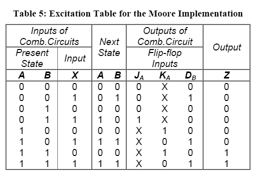
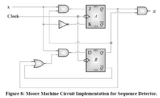
- Simplifying Table 5 using maps, we get the following equations:
o JA = X.B
o KA = X’
o DB =X(A B)
o Z = A . B
- Note that the output is a function of present state values only.
- The circuit diagram for Moore machine circuit implementation is shown in Figure 8.
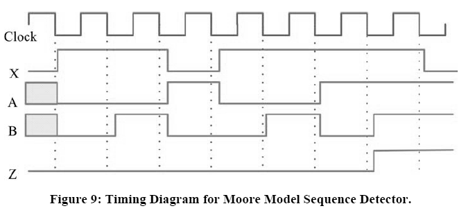
- The timing diagram for Moore machine model is also shown in Figure 9.
- There is no false output in a Moore model, since the output depends only on the state of the flop flops, which are synchronized with clock. The outputs remain valid throughout the logic state in Moore model.