SKEDSOFT
Introduction:
Electronic sensors provide data to the microprocessor in the ECM, which calculates and sends the output signals to the system actuators, which are the fuel pump, fuel injectors and idle air control units. The ECM will also switch some of the exhaust emission and auxiliary system components. ECU and ECM tend to be used interchangeably.
Fuel control electronic control unit (ECU):
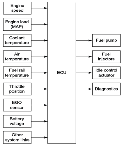
- The ECU is an electronic microcomputer with a central processing unit (CPU) or microprocessor.
- Inside the CPU are software programs that compare all sensor input data with a fixed map of operating conditions.
- It then calculates the required output signal values for the injection valves and other actuators.
- The fixed map of operating conditions specifi c for each engine is held in a fixed value memory or read only memory (ROM).
- The operating data store of input values from the sensors is held in a random access memory (RAM).
Camshaft position sensor:
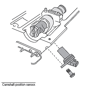
- For sequential injection, a camshaft position sensor is used to recognize the position of number one cylinder.
- The ECU is then able to follow the engine fi ring order. Inductive sensors produce an output pulse each time a lobe or tooth passes the inductive coil.
- The frequency and pattern of the pulses are used by the ECU to determine the engine speed and position.
- The fuel requirement is calculated in the ECU from the engine speed and load conditions.
- An air flow meter is one method of measuring the engine load conditions.
- A variable voltage, corresponding to the measured value at the air flow meter, is used by the ECU to calculate the amount of fuel needed to give a correct air/fuel ratio.
- Often now, engine load is determined from the inlet manifold absolute pressure (MAP). In these systems, an air flow meter is not used.
