SKEDSOFT
Introduction:
Vehicle lighting systems are very important, particularly where road safety is concerned. If head lights were suddenly to fail at night and at high speed, the result could be catastrophic. Many techniques have been used, ranging from automatic changeover circuits to thermal circuit breakers, which pulse the lights rather than putting them out as a blown fuse would.
PARTS OF THE LIGHTING SYSTEM:
- BULBS:
- In the conventional bulb the tungsten filament is heated to incandescence by an electric current. In a vacuum the temperature is about 2300 ° C.
- Gas-filled bulbs are more usual, where the glass bulb is filled with an inert gas such as argon under pressure. This allows the filament to work at a higher temperature without failing and therefore produce a whiter light.
- Almost all vehicles now use tungsten halogen bulbs for their headlights as these are able to produce about 24 lm/W (more for some modern designs). The bulb has a long life and will not blacken over a period of time like other bulbs.
- Cap less bulb: These bulbs have a semi-tubular glass envelope with a flattened end, which provides the support for the terminal wires, which are bent over to form the two contacts. The power rating is up to 5W, and these bulbs are used for panel lights, sidelights and parking.
- EXTERNAL LIGHTS:
- Sidelights (up to 60 cd): A vehicle must have two sidelights each with wattage of less than 7W. Most vehicles have the sidelights incorporated as part of the headlight assembly.
- Rear lights (up to 60 cd): Again, two must be fitted each with wattage not less than 5W.
- Brake lights (40–100 cd): There two lights are often combined with the rear lights. They must be between 15 and 36 W each, with diffused light and must operate when any form of first line brake is applied.
- Reversing lights (300–600 cd): No more than two lights may be fitted with a maximum wattage each of 24W.
- Day running lights: Their function is to indicate that the vehicle is moving or about to move.
- Front spot and fog lights: If front spot lights are fitted (auxiliary driving lights),they must be between 500 and 1200 mm above the ground and more than 400 mm from the side of the vehicle.
- HEAD LIGHT REFLECTORS:
- The object of the headlight reflector is to direct the random light rays produced by the bulb into a beam of concentrated light by applying the laws of reflection.
- Bulb filament position relative to the reflector is important, if the desired beam direction and shape are to be obtained.
- A reflector is basically a layer of silver, chrome or aluminium deposited on a smooth and polished surface such as brass or glass.
- LIGHTING CIRCUITS:
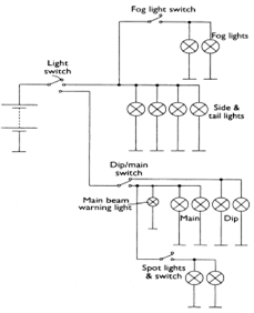
- This representation helps to demonstrate the way in which a lighting circuit operates, it is not is now used in this simple form.
- The circuit does, however, help to show in a simple way how various lights in and around the vehicle operate with respect to each other .For example, fog lights can be wired to work only when the sidelights are on.
- Another example is how the headlights cannot be operated without the side lights first being switched on.
