SKEDSOFT
Generation of Three-phase Balanced Voltages: A polyphase system is basically an ac system composed of a certain number of single-phase ac systems having the same frequency and operating in sequence. Each phase of a polyphase system (i.e., the phase of each single-phase ac system) is displaced from the next by a certain angular interval. In any polyphase system, the value of the angular interval between each phase depends on the number of phases in the system. This manual covers the most common type of polyphase system, the three-phase system. Three-phase systems, also referred to as three-phase circuits, are polyphase systems that have three phases, as their name implies. They are no more complicated to solve than single-phase circuits. In the majority of cases, threephase circuits are symmetrical and have identical impedances in each of the circuit’s three branches (phases). Each branch can be treated exactly as a single-phase circuit, because a balanced three-phase circuit is simply a combination of three single-phase circuits. Therefore, voltage, current, and power relationships for three-phase circuits can be determined using the same basic equations and methods developed for single-phase circuits. Non-symmetrical, or unbalanced, three-phase circuits represent a special condition and their analysis is more complex. Unbalanced three-phase circuits are not covered in detail in this manual.
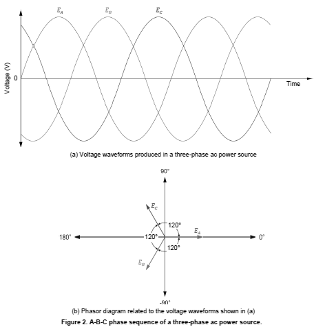
A three-phase ac circuit is powered by three voltage sine waves having the same frequency and magnitude and which are displaced from each other by 120°. The phase shift between each voltage waveform of a three-phase ac power source is therefore 120° (360° ÷ 3 phases). Figure 1 shows an example of a simplified three-phase generator (alternator) producing three-phase ac power. A rotating magnetic field produced by a rotating magnet turns inside three identical coils of wire (windings) physically placed at a 120° angle from each other, thus producing three separate ac voltages (one per winding). Since the generator’s rotating magnet turns at a fixed speed, the frequency of the ac power that is produced is constant, and the three separate voltages attain the maximal voltage value one after the other at phase intervals of 120°.
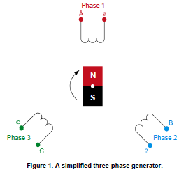
The phase sequence of the voltage waveforms of a three-phase ac power source indicates the order in which they follow each other and attain the maximal
voltage value. Figure 2 shows an example of the voltage waveforms produced in a three-phase ac power source, as well as the phasor diagram related to the
voltage waveforms. The voltage waveforms and voltage phasors in Figure 2 follow the phase sequence EA, EB, EC, which, when written in shorthand form, is the sequence A-B-C. This phase sequence is obtained when the magnet in the three-phase generator of Figure 1 rotates clockwise.
The phase sequence of a three-phase ac power source is important because itdetermines the direction of rotation of any three-phase motor connected to the
power source. If the phases are connected out of sequence, the motor will turn in the opposite direction, and the consequences could be serious. For example, if a three-phase motor rotating in the clockwise direction causes an elevator to go up, connecting the phase wires incorrectly to the motor would cause the elevator to go down when it is supposed to go up, and vice-versa, which could result in a serious accident.