SKEDSOFT
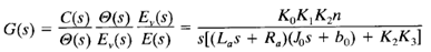
The transfer function between the motor shaft displacement and the error voltage is obtained from Equations above as follows:
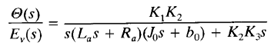


The block diagram of this system can be constructed from Equations above, as shown in Figure 1(b). The transfer function in the feedforward path of this system is
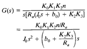
Since La is usually small, it can be neglected, and the transfer function G(s) in the feedforward path becomes
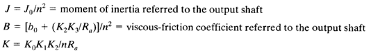
The term [bo (K2K3/Ra)]s indicates that the back emf of the motor effectively increases the viscous friction of the system. The inertia J0 and viscous friction coefficient bo (K2K3/Ra) are referred to the motor shaft. When J0 and bo (K2K3/Ra) are multiplied by 1/n2, the inertia and viscous-friction coefficient are expressed in terms of the output shaft. Introducing new parameters defined by
the transfer function G(s) given by equation above can be simplified, yielding
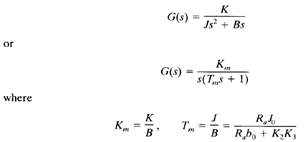
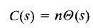
The block diagram of the system shown in Figure 1(b) can thus be simplified as shown in Figure 1(c).
