SKEDSOFT
Lag compensation techniques based on the root-locus approach
Consider the problem of finding a suitable compensation network for the case where the system exhibits satisfactory transient-response characteristics but unsatisfactory steady-state characteristics. Compensation in this case essentially consists of increasing the open loop gain without appreciably changing the transient-response characteristics. This means that the root locus in the neighborhood of the dominant closed-loop poles should not be changed appreciably, but the open-loop gain should be increased as much as needed. This can be accomplished if a lag compensator is put in cascade with the given feedforward transfer function.
To avoid an appreciable change in the root loci, the angle contribution of the lag network should be limited to a small amount, say 5°. To assure this, we place the pole and zero of the lag network relatively close together and near the origin of the s plane. Then the closed-loop poles of the compensated system will be shifted only slightly from their original locations. Hence, the transient-response characteristics will be changed only slightly.
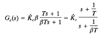
Consider a lag compensator Gc(s), where
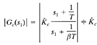
If we place the zero and pole of the lag compensator very close to each other, then at s = s1, where s1 is one of the dominant closed-loop poles, the magnitudes s1 (1/t) and s1 [1/(βT)] are almost equal, or
This implies that if gain  of the lag compensator is set equal to 1 then the transient response characteristics will not be altered. (This means that the overall gain of the open-loop transfer function can be increased by a factor of β where β > 1.) If the pole and zero are placed very close to the origin, then the value of β can be made large. (A large value of β may be used, provided physical realization of the lag compensator is possible.) It is noted that the value of T must be large, but its exact value is not critical.
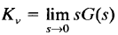
However, it should not be too large in order to avoid difficulties in realizing the phase lag compensator by physical components. An increase in the gain means an increase in the static error constants. If the open loop transfer function of the uncompensated system is G(s), then the static velocity error constant Kv of the uncompensated system is
If the compensator is chosen as given by the equation of Gc(s), then for the compensated system with the open-loop transfer function Gc(s)G(s) the static velocity error constant Kv becomes
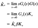
Thus if the compensator is given by Equation, then the static velocity error constant is increased by a factor 
