SKEDSOFT
Lag-lead compensator using operational amplifiers and design
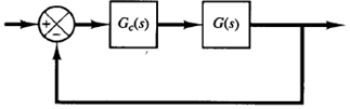
Fig 1: Control system
Consider the system shown in Figure 1. Assume that we use the lag-lead compensator:

where β > 1 and γ > 1. (Consider Kc to belong to the lead portion of the lag-lead compensator.)
In designing lag-lead compensators, we consider two cases where γ ≠ β and γ = β.
Case 1 γ ≠ β:
In this case, the design process is a combination of the design of the lead compensator and that of the lag compensator. The design procedure for the lag-lead compensator follows:
1. From the given performance specifications, determine the desired location for the dominant closed-loop poles.
2. Using the uncompensated open-loop transfer function G(s), determine the angle deficiency Φ if the dominant closed-loop poles are to be at the desired location. The phase-lead portion of the lag-lead compensator must contribute this angle Φ
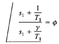
3. Assuming that we later choose T2 sufficiently large so that the magnitude of the lag portion

is approximately unity, where s = s1 is one of the dominant closed-loop poles, choose the values of T1 and γ from the requirement that
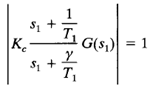
The choice of T1 and γ is not unique. (Infinitely many sets of T1 and γ are possible.) Then determine the value of Kc from the magnitude condition:
4. If the static velocity error constant Kv is specified, determine the value of β to satisfy the requirement for Kv. The static velocity error constant Kv is given by
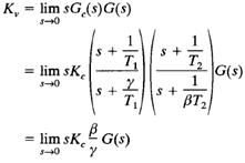
where Kc and γ are already determined in step 3. Hence, given the value of Kv , the value of β can be determined from this last equation.
