SKEDSOFT
Lead compensation techniques based on the root-locus approach
The root-locus approach to design is very powerful when the specifications are given in terms of time-domain quantities, such as the damping ratio and undamped natural frequency of the desired dominant closed-loop poles, maximum overshoot, rise time, and settling time.
Consider a design problem in which the original system either is unstable for all values of gain or is stable but has undesirable transient-response characteristics. In such a case, the reshaping of the root locus is necessary in the broad neighborhood of the jω axis and the origin in order that the dominant closed-loop poles be at desired locations in the complex plane. This problem may be solved by inserting an appropriate lead compensator in cascade with the feedforward transfer function.
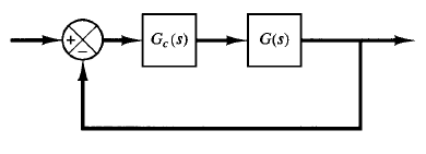
Fig: 1 Control system
The procedures for designing a lead compensator for the system shown in Figure 1 by the root-locus method may be stated as follows:
1. From the performance specifications, determine the desired location for the dominant closed-loop poles.
2. By drawing the root-locus plot, ascertain whether or not the gain adjustment alone can yield the desired closed-loop poles. If not, calculate the angle deficiency Φ. This angle must be contributed by the lead compensator if the new root locus is to pass through the desired locations for the dominant closed-loop poles.
3. Assume the lead compensator Gc(s) to be
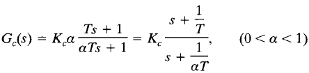
where α and T are determined from the angle deficiency. Kc is determined from the requirement of the open-loop gain.
4. If static error constants are not specified, determine the location of the pole and zero of the lead compensator so that the lead compensator will contribute the necessary angle Φ. If no other requirements are imposed on the system, try to make the value of α as large as possible. A larger value of a generally results in a larger value of Kv, which is desirable. (If a particular static error constant is specified, it is generally simpler to use the frequency-response approach.)
5. Determine the open-loop gain of the compensated system from the magnitude condition.
Once a compensator has been designed, check to see whether all performance specifications have been met. If the compensated system does not meet the performance specifications, then repeat the design procedure by adjusting the compensator pole and zero until all such specifications are met. If a large static error constant is required, cascade a lag network or alter the lead compensator to a lag lead compensator.
Note that if the selected dominant closed-loop poles are not really dominant, it will be necessary to modify the location of the pair of such selected dominant closed-loop poles. (The closed-loop poles other than dominant ones modify the response obtained from the dominant closed-loop poles alone. The amount of modification depends on the location of these remaining closed-loop poles.) Also, the closed-loop zeros affect the response if they are located near the origin.
