SKEDSOFT
Resonant peak magnitude Mr and resonant peak frequency ωr
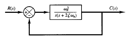
Fig: 1 Control system
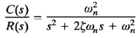
Consider the system shown in Figure 1. The closed-loop transfer function is
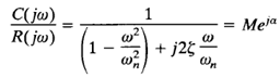
Where  and ωn are the damping ratio and the undamped natural frequency, respectively. The closed-loop frequency response is
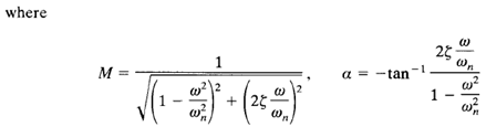
As given by 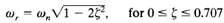 , the maximum value of M occurs at the frequency W r, where
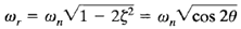
The angle θ is defined in Figure 2. The frequency ωr is the resonant frequency. At the resonant frequency, the value of M is maximum and is given by
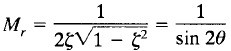
where Mr is defined as the resonant peak magnitude. The resonant peak magnitude is related to the damping of the system.
The magnitude of the resonant peak gives an indication of the relative stability of the system. A large resonant peak magnitude indicates the presence of a pair of dominant closed-loop poles with small damping ratio, which will yield an undesirable transient response. A smaller resonant peak magnitude, on the other hand, indicates the absence of a pair of dominant closed-loop poles with small damping ratio, meaning that the system is well damped.
Remember that ωr is real only if  < 0.707. Thus, there is no closed-loop resonance if > 0.707. [The value of Mr is unity only if > 0.707.] Since the values of Mr and ωr can be easily measured in a physical system, they are quite useful for checking agreement between theoretical and experimental analyses. It is noted, however, that in practical design problems the phase margin and gain margin are more frequently specified than the resonant peak magnitude to indicate the degree of damping in a system.
