SKEDSOFT
Transfer function of the DC motor
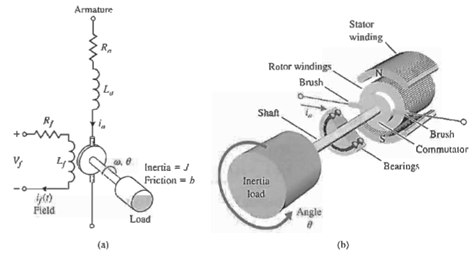
Fig: 1 A DC motor (a) electrical diagram and (b) sketch.
The DC motor is a power actuator device that delivers energy to a load, as shown in Figure 1(a); a sketch of a DC motor is shown in Figure 1(b). The DC motor converts direct current (DC) electrical energy into rotational mechanical energy. A major fraction of the torque generated in the rotor (armature) of the motor is available to drive an external load.
Because of features such as high torque, speed controllability over a wide range, portability, well-behaved speed-torque characteristics, and adaptability to various types of control methods, DC motors are widely used in numerous control applications, including robotic manipulators, tape transport mechanisms, disk drives, machine tools, and servo valve actuators.
The transfer function of the DC motor will be developed for a linear approximation to an actual motor, and second-order effects, such as hysteresis and the voltage drop across the brushes, will be neglected. The input voltage may be applied to the field or armature terminals. The air-gap flux Φ of the motor is proportional to the field current, provided the field is unsaturated, so that

The torque developed by the motor is assumed to be related linearly to Φ and the armature current as follows:
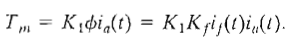
constants of the motor as
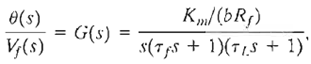
whore τf = Lf/Rf and τL = J/b. Typically, one finds that TL > τf and often the field time constant may be neglected.
