SKEDSOFT
	ITERATIVE-FFT (a)
 1  BIT-REVERSE-COPY (a, A)
 2  n ← length[a]      ▹ n is a power of 2.
 3  for s ← 1 to lg n
 4       do m ← 2s
 5         ωm ← e2πi/m
 6         for k ← 0 to n - 1 by m
 7              do ω ← 1
 8                  for j ← 0 to m/2 - 1
 9                      do t ← ωA[k   j   m/2]
10                         u ← A[k   j]
11                         A[k   j] ← u   t
12                         A[k   j   m/2] ← u - t
13                         ω ← ω ωm
How does BIT-REVERSE-COPY get the elements of the input vector a into the desired order in the array A? The order in which the leaves appear in Figure 30.4 is a bit-reversal permutation. That is, if we let rev(k) be the lg n-bit integer formed by reversing the bits of the binary representation of k, then we want to place vector element ak in array position A[rev(k)]. In Figure 30.4, for example, the leaves appear in the order 0, 4, 2, 6, 1, 5, 3, 7; this sequence in binary is 000, 100, 010, 110, 001, 101, 011, 111, and when we reverse the bits of each value we get the sequence 000, 001, 010, 011, 100, 101, 110, 111. To see that we want a bit-reversal permutation in general, we note that at the top level of the tree, indices whose low-order bit is 0 are placed in the left subtree and indices whose low-order bit is 1 are placed in the right subtree. Stripping off the low-order bit at each level, we continue this process down the tree, until we get the order given by the bit-reversal permutation at the leaves.
Since the function rev(k) is easily computed, the BIT-REVERSE-COPY procedure can be written as follows.
	BIT-REVERSE-COPY(a, A)
1  n ← length[a]
2  for k ← 0 to n - 1
3      do A[rev(k)] ← ak
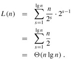
The iterative FFT implementation runs in time Θ(n lg n). The call to BIT-REVERSE-COPY(a, A) certainly runs in O(n lg n) time, since we iterate n times and can reverse an integer between 0 and n - 1, with lg n bits, in O(lg n) time. To complete the proof that ITERATIVE-FFT runs in time Θ(n lg n), we show that L(n), the number of times the body of the innermost loop (lines 8 -13) is executed, is Θ(n lg n). The for loop of lines 6 -13 iterates n/m = n/2s times for each value of s, and the innermost loop of lines 8 -13 iterates m/2 = 2s-1 times. Thus,
A parallel FFT circuit: We can exploit many of the properties that allowed us to implement an efficient iterative FFT algorithm to produce an efficient parallel algorithm for the FFT. We will express the parallel FFT algorithm as a circuit that looks much like the comparison networks of Sorting Networks. Instead of comparators, the FFT circuit uses butterfly operations, as drawn in Figure 30.3(b). The notion of depth that we developed in Sorting Networks applies here as well. The circuit PARALLEL-FFT that computes the FFT on n inputs is shown in Figure 30.5 for n = 8. It begins with a bit-reverse permutation of the inputs, followed by lg n stages, each stage consisting of n/2 butterflies executed in parallel. The depth of the circuit is therefore Θ(lg n).
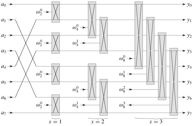
Figure 30.5: A circuit PARALLEL-FFT that computes the FFT, here shown on n = 8 inputs. Each butterfly operation takes as input the values on two wires, along with a twiddle factor, and it produces as outputs the values on two wires. The stages of butterflies are labeled to correspond to iterations of the outermost loop of the ITERATIVE-FFT procedure. Only the top and bottom wires passing through a butterfly interact with it; wires that pass through the middle of a butterfly do not affect that butterfly, nor are their values changed by that butterfly. For example, the top butterfly in stage 2 has nothing to do with wire 1 (the wire whose output is labeled y1); its inputs and outputs are only on wires 0 and 2 (labeled y0 and y2, respectively). An FFT on n inputs can be computed in Θ(lg n) depth with Θ(n lg n) butterfly operations.
The leftmost part of the circuit PARALLEL-FFT performs the bit-reverse permutation, and the remainder mimics the iterative ITERATIVE-FFT procedure. Because each iteration of the outermost for loop performs n/2 independent butterfly operations, the circuit performs them in parallel. The value of s in each iteration within ITERATIVE-FFT corresponds to a stage of butterflies shown in Figure 30.5. Within stage s, for s = 1, 2,..., lg n, there are n/2s groups of butterflies (corresponding to each value of k in ITERATIVE-FFT), with 2s-1 butterflies per group (corresponding to each value of j in ITERATIVE-FFT). The butterflies shown in Figure 30.5 correspond to the butterfly operations of the innermost loop (lines 9 -12 of ITERATIVE-FFT). Note also that the twiddle factors used in the butterflies correspond to those used in ITERATIVE-FFT: in stage s, we use  , where m = 2s.
