SKEDSOFT
Augmenting paths: Given a flow network G = (V, E) and a flow f, an augmenting path p is a simple path from s to t in the residual network Gf. By the definition of the residual network, each edge (u, v) on an augmenting path admits some additional positive flow from u to v without violating the capacity constraint on the edge.
The shaded path in Figure 26.3(b) is an augmenting path. Treating the residual network Gf in the figure as a flow network, we can increase the flow through each edge of this path by up to 4 units without violating a capacity constraint, since the smallest residual capacity on this path is cf(v2, v3) = 4. We call the maximum amount by which we can increase the flow on each edge in an augmenting path p the residual capacity of p, given by
cf (p) = min {cf(u, v) : (u, v) is on p}.
Cuts of flow networks
The Ford-Fulkerson method repeatedly augments the flow along augmenting paths until a maximum flow has been found. The max-flow min-cut theorem, which we shall prove shortly, tells us that a flow is maximum if and only if its residual network contains no augmenting path. To prove this theorem, though, we must first explore the notion of a cut of a flow network.
A cut (S, T) of flow network G = (V, E) is a partition of V into S and T = V - S such that s ∈ S and t ∈ T. (This definition is similar to the definition of "cut" that we used for minimum spanning trees in Minimum Spanning Trees, except that here we are cutting a directed graph rather than an undirected graph, and we insist that s ∈ S and t ∈ T.) If f is a flow, then the net flow across the cut (S, T) is defined to be f(S, T). The capacity of the cut (S, T) is c(S, T). A minimum cut of a network is a cut whose capacity is minimum over all cuts of the network.
Figure 26.4 shows the cut ({s, v1, v2}, {v3, v4, t}) in the flow network of Figure 26.1(b). The net flow across this cut is
|
f(v1, v3) f(v2, v3) f(v2, v4) |
= |
12 (-4) 11 |
|
= |
19, |
and its capacity is
|
c(v1, v3) c(v2, v4) |
= |
12 14 |
|
= |
26. |
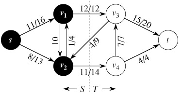
Observe that the net flow across a cut can include negative flows between vertices, but that the capacity of a cut is composed entirely of nonnegative values. In other words, the net flow across a cut (S, T) consists of positive flows in both directions; positive flow from S to T is added while positive flow from T to S is subtracted. On the other hand, the capacity of a cut (S, T) is computed only from edges going from S to T. Edges going from T to S are not included in the computation of c(S, T).
