SKEDSOFT
This time steps 1 and 2 produce the following results. Only node 4 is labeled from node 1, with [4, 1].
Node 5 is the only node labeled from node 4, with [3, 4] step 3 begins with Fig. (4.54).
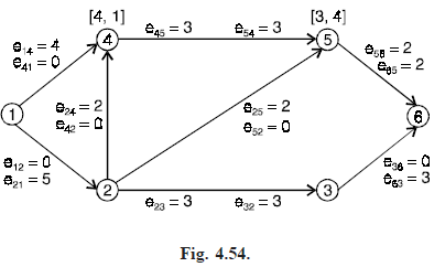
At this point, node 5 could label node 2 using the excess capacity of edge (5, 2).
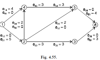
However, node 5 can also be used to label the sink. The sink is labeled [2, 5] and the total flow is increased to 7 units. In step 5, we work back along the path 1, 4, 5, 6, adjusting excess capacities. We return to step 1 with the configuration shown in Fig. (4.55).
Verify that after steps 1, 2 and 3, nodes 4, 5 and 2 have been labeled as shown in Fig. (4.56) and no further labeling is possible. The final labeling of node 2 uses the virtual edge (5, 2).
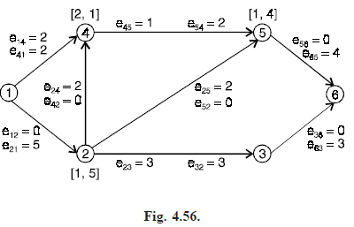
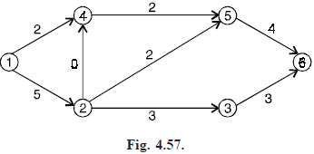
Thus, the final overall flow has value 7. By subtracting the final excess capacity eij of each edge (i, j) in N from the capacity Cij, the flow F that produces the maximum value 7 can be see in Fig. (4.57).