SKEDSOFT
Amplifiers
The level of an electrical signal can be represented by variables such as voltage, current, and power. Analogous across variables, through variables, and power variables can be defined for other types of signals (e.g., mechanical) as well.
Signal levels at various interface locations of components in a mechatronic system have to be properly adjusted for satisfactory performance of these components and of the overall system.
For example, input to an actuator should possess adequate power to drive the actuator.
A signal should maintain its signal level above some threshold during transmission so that errors due to signal weakening would not be excessive.
Signals applied to digital devices must remain within the specified logic levels. Many types of sensors produce weak signals that have to be upgraded before they could be fed into a monitoring system, data processor, controller, or data logger. Signal amplification concerns proper adjustment of the signal level for performing a specific task. Amplifiers are used to accomplish signal amplification.
An amplifier is an active device that needs an external power source to operate.
Even though various active circuits, amplifiers in particular, are commonly produced in the monolithic form using an original integrated-circuit (IC) layout so as to accomplish a particular amplification task, it is convenient to study their performance formance using discrete circuit models with the operational amplifier (op-amp) as the basic building block.
Of course, operational amplifiers are themselves available as monolithic IC packages.
They are widely used as the basic building blocks in producing other types of amplifiers, and in turn for modeling and analyzing these various kinds of amplifiers. For these reasons, our discussion on amplifiers will evolve from the operational amplifier.
Operational Amplifier
The origin of the operational amplifier dates back to the 1940s when the vacuum tube operational amplifier was introduced. Operational amplifier or op-amp got its name due to the fact that originally it was used almost exclusively to perform mathematical operations; for example, in analog computers. Subsequently, in the 1950s the transistorized op-amp was developed. It used discrete elements such as bipolar junction transistors and resistors.
Still it was too large in size, consumed too much power, and was too expensive for widespread use in general applications. This situation changed in the late 1960s when integrated-circuit (IC) op-amp was developed in the monolithic form, as a single IC chip.
Today, the IC op-amp, which consists of a large number of circuit elements on a substrate of typically a single silicon crystal (the monolithic form), is a valuable component in almost any signal modification device. Bipolar-CMOS (complementary metal oxide semiconductor) op-amps in various plastic packages and pin configurations are commonly available.
An op-amp could be manufactured in the discrete-element form using, say, ten bipolar junction transistors and as many discrete resistors or alternatively (and preferably) in the modern monolithic form as an IC chip that may be equivalent to over 100 discrete elements.
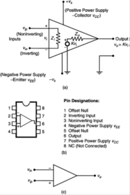
In any form, the device has an input impedance Zi, an output impedance Zo and a gain K. Hence, a schematic model for an op-amp can be given as in Figure (a). Op-amp packages are available in several forms. Very common is the 8-pin dual in-line package (DIP) or V package, as shown in Figure (b).
The assignment of the pins (pin configuration or pinout) is as shown in the figure, which should be compared with Figure (a). Note the counter-clockwise numbering sequence starting with the top left pin next to the semicircular notch (or, dot). This
In analyzing operational amplifier circuits under unsaturated conditions, we use the following two characteristics of an op-amp:
1. Voltages of the two input leads should be (almost) equal
2. Currents through each of the two input leads should be (almost) zero
