SKEDSOFT
Analog-To-Digital Converters:
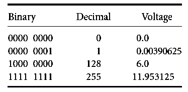
The ADC can basically be typed by two parameters: the analog input range and the digital output range. As an example, consider an ADC that is converting a voltage level ranging 0–12 V into a single byte of 8 bits.
Each binary count increment reflects an increase in analog voltage of 1/256 of the maximum 12 V. There is an unusual twist to this conversion, however.
Since a zero value represents 0 V, and a 128 value represents half of the maximum value, 6 V in this example, the maximum decimal value of 255 represents 255/256 of the maximum voltage value, or 11.953125 V. A table of the equivalent values is shown below:
An ADC that is implemented in the Motorola HC12 microcontroller produces 10 bits. While not fitting so nicely into a single byte of data, this 10-bit ADC does give additional resolution.
Using an input range from 0 to 5 V, the decimal resolution per least significant bit is 4.88 mV. If the ADC had 8 bits of output, the resolution per bit would be 19.5 mV, a fourfold difference.
Larger voltages, e.g., from 0 to 12 V, can be scaled with a voltage divider to fit the 0–5 V range. Smaller voltages can be amplified to span the entire range.
A process known as successive approximation (using the Successive Approximation Register or SAR in the Motorola chip) is used to determine the correct digital value.
