SKEDSOFT
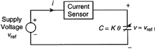
Capacitive Angular Velocity Sensor
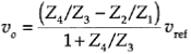
The schematic diagram for an angular velocity sensor that uses a rotating-plate capacitor. Since the current sensor has negligible resistance, the voltage across the capacitor is almost equal to the supply voltage uref, which is kept constant. It follows that the current in the circuit is given by
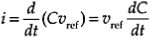

This is a linear relationship for angular velocity in terms of the measured current i. Care must be exercised to ensure that the current-measuring device does not interfere with (e.g., does not load) the basic circuit.
An advantage of capacitance transducers is that because they are no contacting devices, mechanical loading effects are negligible.
There is some loading due to inertial forces of the moving plate and frictional resistance
in associated sliding mechanisms, bearings, etc. Such influences can be eliminated by using the moving object itself as the moving plate.
Variations in the dielectric properties due to humidity, temperature, pressure, and impurities introduce errors. A capacitance bridge circuit can compensate for these effects.
Capacitance Bridge Circuit
Sensors that are based on the change in capacitance (reactance) will require some means of measuring that change. Furthermore, changing capacitance that is not caused by a change in measurand, for example, due to change in humidity, temperature, etc, will cause errors and should be compensated for. Both these goals are accomplished using a capacitance bridge circuit.
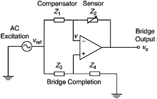
A bridge circuit for capacitive sensors.