SKEDSOFT
Charge Amplifier
Piezoelectric signals cannot be read using low-impedance devices. The two primary reasons for this are:
1. High output impedance in the sensor results in small output signal levels and large loading errors.
2. The charge can quickly leak out through the load.
A charge amplifier is commonly used as the signal-conditioning device for piezoelectric sensors, in order to overcome these problems to a great extent.
Because of impedance transf formation, the impedance at the output of the charge amplifier becomes much smaller than the output impedance of the piezoelectric sensor.
This virtually eliminates loading error and provides a low-impedance output for purposes such as signal communication, acquisition, recording, processing, and control. Also, by using a charge amplifier circuit with a relatively large time constant, speed of charge leakage can be decreased.
The capacitance of the cable, which connects the sensor to the charge amplifier, is denoted by A piezoelectric sensor and charge amplifier combination.
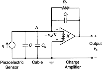
A piezoelectric sensor and charge amplifier combination.
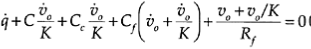
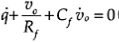
For an unsaturated opamp of gain K, the voltage at its inverting (negative) input is -uo/K, where uo is the voltage at the amplifier output. Note that the noninverting (positive) input of the opamp is grounded (i.e., maintained at zero potential). Due to very high input impedance of the opamp, the currents through its input leads will be negligible. Current balance at point A gives:
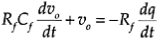
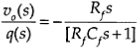
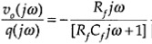
Note that the output is zero at zero frequency (w=0). Hence, a piezoelectric sensor cannot be used for measuring
constant (dc) signals.
At very high frequencies, on the other hand, the transfer function approaches the constant value -1/Cf. which is the calibration constant for the device.
