SKEDSOFT
Data Acquisition Hardware
A method for interfacing an incremental encoder to a digital processor (digital controller) In practice, a suitable interface card (e.g., servo card, encoder card, etc.) in the control computer will possess the necessary functional capabilities indicated in the figure.
The pulse signals from the encoder are fed into an up/down counter, which has circuitry to detect pulses (e.g., by rising-edge detection, falling-edge detection, or by level detection) and logic circuitry to determine the direction of motion (i.e., sign of the reading) and to code the count.
A pulse in one direction (say, clockwise will increment the count by one (an up count), and a pulse in the opposite direction will Computer interface for an incremental encoder.
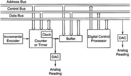
The coded count may be directly read by the host computer, through its input/output (I/O) board without the need for an analog to digital converter (ADC).
The count is transferred to a latch buffer so that the measurement is read from the buffer rather than from the counter itself.
This arrangement provides an efficient means of data acquisition because the counting process can continue without interruption while the computer reads the count from the latch buffer.
The digital processor (computer) identifies various components in the measurement system using addresses, and this information is communicated to the individual components through the address bus.
The start, end, and nature of an action (e. g., data read, clear the counter, clear the buffer) are communicated to various devices by the computer through its control bus. The computer can command an action to a component in one direction of the bus, and the component can respond with a message (e.g., job completed) in the opposite direction.
The data (e.g., the count) are transmitted through the data bus. While the computer reads (samples) data from the buffer, the control signals guarantee that no data are transferred to that buffer from the counter.
It is clear that the data acquisition consists of handshake operations between the main processor of the computer and auxiliary components. More than one encoder may be addressed, controlled, and read by the same three buses of the computer.
The buses are conductors, for example, multicore cables carrying signals in parallel logic. Communication in serial logic is also common but is slower.
An incremental optical encoder generates two pulse signals one 1/4 of a pitch out of phase with the other. The internal electronics of the encoder may be powered by a 5 V dc supply The two pulse signals determine the direction of rotation of the motor by one of various means (e.g., sign of the phase difference, timing of the consecutive rising edges).
The encoder pulse count is stored in a buffer within the controller and is read at fixed intervals (say, 5 ms). The net count gives the joint position, and the difference in count at a fixed time increment gives joint speed.
