SKEDSOFT
DC Tachometer
This is a permanent-magnet dc velocity sensor in which the principle of electromagnetic induction between a permanent magnet and a conducting coil is used.
Depending on the configuration, either rectilinear speeds or angular speeds can be measured. Schematic diagrams of the two configurations.
Note that these are passive transducers, because the energy for the output signal uo is derived from the motion
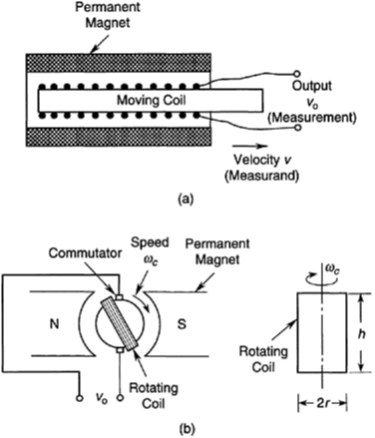
Permanent-magnet dc transducers: (a) Rectilinear velocity transducer; (b) DC tachometer
The entire device is usually enclosed in a steel casing to shield (isolate) it from ambient magnetic fields.
The conductor coil is wound on a core and placed centrally between two magnetic poles, which produce a crossmagnetic field. The core is attached to the moving object whose velocity u must be measured.
This velocity is proportional to the induced voltage uo.
Alternatively, a moving magnet and a fixed coil may be used as a dc tachometer. This arrangement is perhaps more desirable since it eliminates the need for any sliding contacts (slip rings and brushes) for the output leads, thereby reducing mechanical loading error, wear, and related problems.
The dc tachometer (or, tachogenerator) is a common transducer for measuring angular velocities.
Its principle of operation is the same as that for a dc generator (or, back-driving of a dc motor).
Electronic Commutation
Slip rings and brushes and associated drawbacks can be eliminated in a dc tachometer by using electronic commutation. In this case a permanent-magnet rotor together with a set of stator windings is used.
The output of the tachometer is drawn from the stationary (stator) coil.
