SKEDSOFT
The generated voltage ug at the armature (rotor) is proportional to the magnetic field strength of field windings
Uo=Kwi
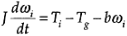
The rotor magnetic torque TG, which resists that applied torque Ti, is proportional to the magnetic field strengths of the field windings and armature windings.
Note that the same constant K is used in both Equation i and Equation ii.
This is valid when the same units are used to measure mechanical power and electrical power and when the internal energy-dissipation mechanisms are not significant in the associated internal coupling.
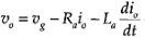
The equation for the armature circuit is
Now Equation i is substituted into Equation iii in order to eliminate ug. Similarly, Equation ii is substituted into
Equation in order to eliminate Tg.
Next, the time derivatives are replaced by the Laplace variable s. This results in the two algebraic relations:
(b sJ) WI=Ti-Kio
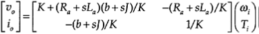
Note that the variables ui, Io, WI, and Ti in Equation v and Equation vi are actually Laplace transforms (functions of s), not functions of t, as in Equations i through iv. Finally, io in Equation v is eliminated using Equation vi. This gives the matrix transfer function relation
The corresponding frequency domain relations are obtained by replacing s with jw, where w represents the angular frequency (radians/second) in the frequency spectrum of a signal.
Even though transducers are more accurately modeled as two-port elements, which have two variables associated with each port, it is useful and often essential, for practical reasons, to relate just one input variable (measurand) and one output variable (measurement) so that only one (scalar) transfer function relating these two variables need be specified. This assumes some form of decoupling in the true model.
If this assumption does not hold in the range of operation of the transducer, a measurement error would result. In particular, for a tachometer, we like to express the output voltage uo in terms of the measured speed WI. In this case, the off diagonal term - (Ra sLa)/K in Equation vii has to be neglected.
This is valid when the tachometer gain parameter K is large and the armature resistance Ra is negligible, since the leakage inductance La is negligible in any case for most practical purposes. Note from Equation i and Equation ii that the tachometer gain K can be increased by increasing the field current iƒ.
This will not be feasible if the field windings are already saturated, however. Furthermore, K (or K¢) depends on parameters such as number of turns and dimensions of the stator windings and magnetic properties of the stator core. Since there is a limitation on the physical size of the tachometer and the types of materials used in the construction, it is clear that K cannot be increased arbitrarily.
The instrument designer should take such factors into consideration in developing a design that is optimal in many respects. In practical transducers, the operating range is specified in order to minimize the effect of coupling terms, and the residual errors are accounted for by using correction curves. This approach is more convenient than using a coupled model, which introduces three more (scalar) transfer functions (in general) into the model.
Another desirable feature for practical transducers is to have a static (algebraic, no dynamic) input/output relationship so that the output instantly reaches the input value (or the measured variable).
In this case, the transducer transfer function is a pure gain. This happens when the transducer time constants are small (i.e., the transducer bandwidth is high). In the present tachometer example, it is clear from Equation vii that the transfer function relations become static (frequency-independent) when both electrical time constant:


