SKEDSOFT
Digital Resolvers
Digital resolvers, or mutual induction encoders, operate somewhat like analog resolvers, using the principle of mutual induction. They are known commercially as Inductosyns.
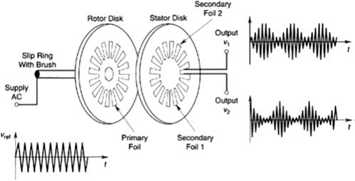
A digital resolver has two disks facing each other (but not in contact), one (the stator) stationary and the other (the rotor) coupled to the rotating object whose motion is measured. The rotor has a fine electric conductor foil imprinted on it, as schematically.
The printed pattern is “pulse” shaped, closely spaced, and connected to a high-frequency ac supply (carrier) of voltage uref. The stator disk has two separate printed patterns that are identical to the rotor pattern, but one pattern on the stator is shifted by a quarter-pitch from the other pattern.
The primary voltage in the rotor circuit induces voltages in the two secondary (stator) foils at the same frequency, that is, the rotor and the stator are inductively coupled.
These induced voltages are “quadrature” signals. As the rotor turns, the level of the induced voltage changes, depending on the relative position of the foil patterns on the two disks.
When the foil pulse patterns coincide, the induced voltage is a maximum (positive or negative), and when the rotor foil pattern has a half pitch offset from the stator foil pattern, the induced voltages in the adjacent segments cancel each other, producing a zero output. The output (induced) voltages u1 and u2 in the corresponding to the rotation of the disk.
The latter (modulating component) can be extracted through demodulation, and converted into a proper pulse signal using pulse-shaping circuitry, as for an incremental encoder. When the rotating speed is constant, the two modulating components are periodic and nearly sinusoidal, with a phase shift of 90° (i.e., in quadrature). When the speed is not constant, the pulse width will vary with time.
As in the case of an incremental encoder, angular displacement is determined by counting the pulses.
Furthermore, angular velocity is determined either by counting the pulses over a fixed time period (counter sampling period) or by timing the pulses. The direction of rotation is determined by the phase difference in the two modulating (output) signals. (In one direction, the phase shift is 90°; in the other direction, it is -90°.) Very fine resolutions (e.g., 0.0005°) may be obtained from a digital resolver, and it is usually not necessary to use step-up gearing or other techniques to improve the resolution.
These transducers are usually more expensive than optical encoders. The use of a slip ring and brush to supply the carrier signal may be viewed as a disadvantage.
