SKEDSOFT
Introduction:
High resolution (depending on the word size of the encoder output and the number of pulses generated per revolution of the encoder), high accuracy (particularly due to noise immunity and reliability of digital signals and superior construction), and relative ease of adoption in digital control systems (because transducer output can be read as a digital word), with associated reduction in system cost and improvement of system reliability, are some of the relative advantages of digital transducers in general and shaft encoders in particular, in comparison to their analog counterparts.
The same signal generation (and pick-off) mechanism may be used in both types of transducers. Four techniques of transducer signal generation can be identified:
1. Optical (photo sensor) method
2. Sliding contact (electrical conducting) method
3. Magnetic saturation (reluctance) method
4. Proximity sensor method
By far, the optical encoder is most popular and cost effective. The other three approaches may be used in special circumstances where an optical may not be suitable (e.g., under extreme temperatures) or may be redundant (e.g., where a code disk such as a toothed wheel is already available as an integral part of the moving member).
For a given type of encoder (incremental or absolute), the method of signal interpretation is identical for all four types of signal generation listed above. We will briefly describe the principle of signal generation for all four techniques, and will consider only the optical encoder in the context of signal interpretation and processing.
The optical encoder uses an opaque disk (code disk) that has one or more circular tracks, with some arrangement of identical transparent windows (slits) in each track.
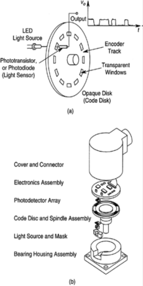 A parallel beam of light (e.g., from a set of light-emitting diodes or LEDs) is projected to all tracks from one side of the disk. The transmitted light is picked off using a bank of photo sensors on the other side of the disk, which typically has one sensor for each track. This arrangement is shown in Figure (a), which indicates just one track and one pick-off sensor. The light sensor could be a silicon photodiode or a phototransistor.
Since the light from the source is interrupted by the opaque regions of the track, the output signal from the photo sensor is a series of voltage pulses.
This signal can be interpreted (e.g., through edge detection or level detection) to obtain the increments in the angular position and also angular velocity of the disk.
Note that in the standard terminology, the sensor element of such a measuring device is the encoder disk, which is coupled to the rotating object (directly or through a gear mechanism). The transducer stage is the conversion of disk motion (analog) into the pulse signals (which can be coded into a digital word).
The opaque background of transparent windows (the window pattern) on an encoder disk may be produced by contact printing techniques.
The precision of this production procedure is a major factor that determines the accuracy of optical encoders.
Note that a transparent disk with a track of opaque spots will work equally well as the encoder disk of an optical encoder. In either form, the track has a 50% duty cycle.
