SKEDSOFT
Encoder Error
Errors in shaft encoder readings can come from several factors. The primary sources of these errors are as follows:
1. Quantization error (due to digital word size limitations)
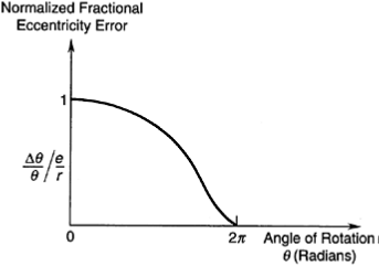
2. Assembly error (eccentricity of rotation, etc.)
3. Coupling error (gear backlash, belt slippage, loose fit, etc.)
4. Structural limitations (disk deformation and shaft deformation due to loading)
5. Manufacturing tolerances (errors from inaccurately imprinted code patterns, inexact positioning of the pickoff sensors, limitations and irregularities in signal generation and sensing hardware, etc.)
6. Ambient effects (vibration, temperature, light noise, humidity, dirt, smoke, etc.)
These factors can result in inexact readings of displacement and velocity, and erroneous detection of the
direction of motion.
One form of error in encoder readings is the hysteresis. For a given position of the moving object, if the encoder reading depends on the direction of motion, the measurement has a hysteresis error. In that case, if the object rotates from position A to position B and back to position A, for example, the initial and the final readings of the encoder will not match.
The causes of hysteresis include backlash in gear couplings, loose fits, mechanical deformation in the code disk and shaft, delays in electronic circuitry and components (electrical time constants, nonlinearities, etc.), magnetic hysteresis (in the case of a magnetic encoder), and noisy pulse signals that make the detection of pulses (say, by level detection or edge detection) less accurate.
The raw pulse signal from an optical encoder is somewhat irregular and does not consist of perfect pulses, primarily because of the variation (somewhat triangular) of the intensity of light received by the optical sensor as the code disk moves through a window, and because of noise in the signal generation circuitry, including the noise created by imperfect light sources and photo sensors. Noisy pulses have imperfect edges. As a result, pulse detection through edge detection can result in errors such as multiple triggering for the same edge of a pulse.
This can be avoided by including a Schmitt trigger (a logic circuit with electronic hysteresis) in the edge detection circuit, so that slight irregularities in the pulse edges will not cause erroneous triggering, provided that the noise level is within the hysteresis band of the trigger.
A disadvantage of this method, however, is that hysteresis will be present even when the encoder itself is perfect. Virtually noise-free pulses can be generated if two photosensors are used to detect adjacent transparent and opaque areas on a track simultaneously and a separate circuit (a comparator) is used to create a pulse that depends on the sign of the voltage difference of the two sensor signals.
Miscellaneous Digital Transducers
Now several other types of digital transducers, which are useful in the mechatronics practice, are described. In particular, digital rectilinear transducers are described.
These are useful in many applications. Typical applications include x-y positioning tables, machine tools, valve actuators, read-write heads in disk drive systems, and robotic manipulators (e.g., at prismatic joints) and robot hands.
