SKEDSOFT
Hardware Features
A more detailed schematic diagram of the signal generation mechanism of an optical incremental encoder is shown in Figure (a).
The light generated by the light-emitting diode (LED) is collimated (forming parallel rays) using a lens. This pencil of parallel light passes through a window of the rotating code disk. The masking (grating) disk is stationary and has a track of windows identical to that in the code disk.
Because of the presence of the masking disk, light from the LED will pass through more than one window of the code disk, thereby improving the intensity of light received by the photosensor but not introducing any error due to the diameter of
the pencil of light being larger than the window length.
When the windows of the code disk face the opaque an area of the masking disk, virtually no light is received by the photosensor. When the windows of the code disk face the transparent areas of the masking disk, maximum amount of light reaches the photosensor.
Hence, as the code disk moves, a sequence of triangular (and positive) pulses of light is received by the photosensor. Pulse width in this case is a full cycle (i.e., it corresponds to the window pitch) and not a half cycle.
Fluctuation in the supply voltage to the encoder light source also directly influence the light level received by the photosensor. If the sensitivity of the photosensor is not high enough, a low light level might be interpreted as no light, this would result in measurement error.
Such errors due to instabilities and changes in the supply voltage, can be eliminated by using two photo sensors, one placed half a pitch away from the other along the window track.
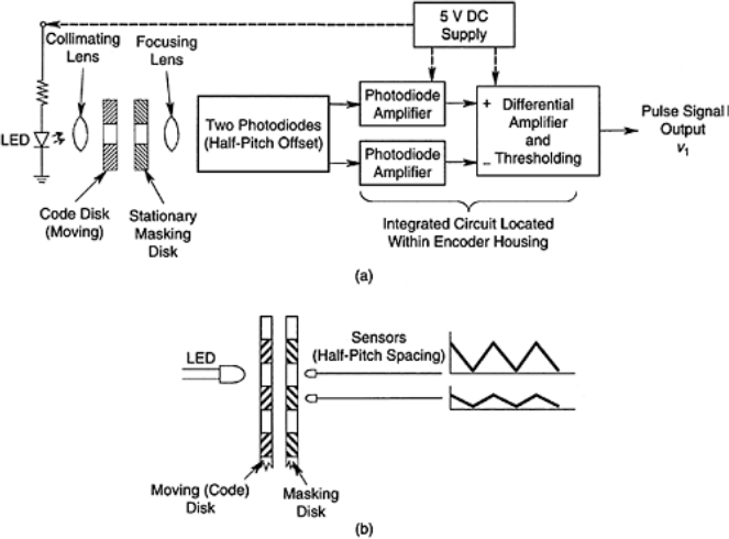
The sensor facing the opaque region of the masking disk will always read a low signal.
The other sensor will read a triangular signal whose peak occurs when a moving widow overlaps with a window of the masking disk, and whose valley occurs when a moving window faces an opaque region of the masking disk. The two signals from these two sensors are amplified separately and fed into a differential amplifier.
The result is a high-intensity triangular pulse signal. A shaped (or, binary) pulse signal can be generated by subtracting a threshold value from this signal and identifying the resulting positive (or, binary 1) and negative (or, binary 0) regions.
This procedure will produce a more distinct (or, binary) pulse signal that is immune to noise.
The signal amplifiers are integrated circuit devices and are housed within the encoder itself. Additional pulse shaping circuitry may also be present.
