SKEDSOFT
Harmonic Drives
Usually, motors run efficiently at high speeds. Yet in many practical applications, low speeds and high torques are needed.
A straightforward way to reduce the effective speed and increase the output torque of a motor is to employ a gear system with high gear reduction.
Gear transmission has several disadvantages, however. For example, backlash in gears would be unacceptable in high-precision applications.
Frictional loss of torque, wear problems, and the need for lubrication must also be considered. Furthermore, the mass of the gear system consumes energy from the actuator (motor), and reduces the overall torque/mass ratio and the useful bandwidth of the actuator.
A harmonic drive is a special type of transmission device that provides very large speed reductions (e.g., 200:1) without backlash problems.
Also, a harmonic drive is comparatively
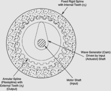
The principle of operation of a harmonic drive. much lighter than a standard gearbox. The harmonic drive is often integrated with conventional motors to provide very high torques, particularly in direct-drive and servo applications. The principle of operation of a harmonic drive is shown in Figure.
The rigid circular spline of the drive is the outer gear and it has internal teeth. An annular flexispline has external teeth that can mesh with the internal teeth of the rigid spline in a limited region when pressed in the radial direction.
The external radius of the flexispline is slightly smaller than the internal radius of the rigid spline. As its name implies, the flexispline undergoes some elastic deformation during the meshing process.
This results in a tight mesh without any clearance between meshed teeth, and hence the motion is backlash free.
In the design shown in Figure, the rigid spline is fixed and may also serve as the housing of the harmonic drive.
The rotation of the flexispline is the output of the drive; hence, it is connected to the driven load. The input shaft (motor shaft) drives the wave generator.
The wave generator motion brings about controlled backlash-free meshing between the rigid spline and the flexispline.
Suppose that
nr=number of teeth (internal) in the rigid spline
nƒ=number of teeth (external) in the flexispline
It follows that
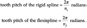
Further, suppose that nr is slightly smaller than nf. Then, during a single tooth engagement, the flexispline rotates through (2p/nr-2p/nƒ)radians in the direction of rotation of the wave generator. During one full rotation of the wave generator, there will be a total of nr tooth engagements in the rigid spline (which is stationary in this design). Hence, the rotation of the flexispline during one rotation of the wave generator.
