SKEDSOFT
There are two possible configurations for an incremental encoder disk:
1. Offset sensor configuration
2. Offset track configuration
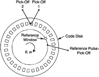 The disk has a single circular track with identical and equally spaced transparent windows. The area of the opaque region between adjacent windows is equal to the window area.
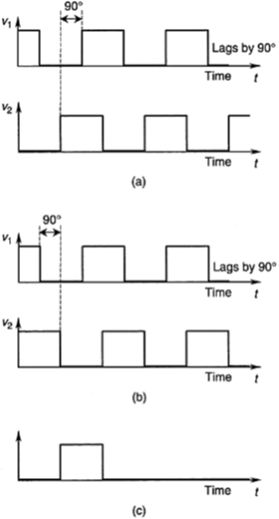
Shaped pulse signals from an incremental encoder: (a) For clockwise rotation; (b) For counterclockwise
rotation; (c) Reference pulse signal.
Each track has its own pick-off sensor, oriented normally facing the track.
The two pick-off sensors are positioned on a radial line facing the disk, without any circumferential offset unlike the previous configuration.
The output signals from the two sensors are the same as before, however. Note that an output pulse signal is on half the time and off half the time, giving a 50% duty cycle.
In both configurations, an additional track with a lone window and associated sensor is also usually available. This track generates a reference pulse (index pulse) per revolution of the disk.
This pulse is used to initiate the counting operation. Furthermore, the index pulse count gives the number of complete revolutions, which is required in measuring absolute angular rotations.
Note that when the disk rotates at constant angular speed, the pulse width and pulse-to-pulse period (encoder cycle) are constant (with respect to time) in each sensor output.
When the disk accelerates, the pulse width decreases continuously; when the disk decelerates, the pulse width increases.
