SKEDSOFT
Linear Encoders
In rectilinear encoders (popularly called linear encoders, where “linear” does not imply linearity but refers to rectilinear motion) rectangular flat plates moving rectilinearly, instead of rotating disks, are used with the same types of signal generation and interpretation mechanisms as for shaft (rotatory) encoders.
A transparent plate with a series of opaque lines arranged in parallel in the transverse direction forms the stationary plate (grating plate or phase plate) of the transducer. This is called the mask plate.
A second transparent plate, with an identical set of ruled lines, forms the moving plate (or the code plate). The lines on both plates are evenly spaced, and the line width is equal to the spacing between adjacent lines.
A light source is placed on the moving plate side, and light transmitted through the common area of the two plates is detected on the other side using one or more photosensors.
When the lines on the two plates coincide, the maximum amount of light will pass
through the common area of the two plates. When the lines on one plate fall on the transparent spaces of the other plate, virtually no light will pass through the plates.
Accordingly as one plate moves relative to the other, a pulse train is generated by the photosensor, and it can be used to determine rectilinear displacement and velocity, as in the case of an incremental encoder.
A suitable arrangement.
The code plate is attached to the moving object whose rectilinear motion is to be measured. An LED light source and a photo-transistor light sensor are used to detect the motion pulses, which can be interpreted just like in the case of a rotatory encoder.
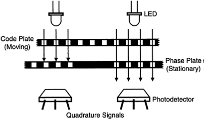
The phase plate is used, as with a shaft encoder, to enhance the intensity and the discrimination of the detected signal.
Two tracks of windows in quadrature (i.e., 1/4 pitch offset) would be needed to determine the direction of motion Another track of windows at pitch offset with the main track may be used as well on the phase plate, to further enhance the discrimination of the detected pulses.
Specifically, when the sensor at the main track reads a high intensity (i. e., when the windows on the code plate and the phase plate are aligned) the sensor at the track that is pitch away will read a low intensity (because the corresponding windows of the phase plate are blocked by the solid regions of the code plate).
