SKEDSOFT
Linear-Variable Differential Transformer (LVDT)
Differential transformer is a noncontact displacement sensor, which does not possess many of the shortcomings of the potentiometer.
 It is a variable-inductance transducer, and is also a variable-reluctance transducer and a mutual-induction transducer. Furthermore, unlike the potentiometer, the differential transformer is a passive device.
First we will discuss the linear-variable differential transformer, which is used for measuring rectilinear (or translatory) displacements. Next we will describe the rotatory-variable differential transformer (RVDT), which is used for measuring angular (or rotatory) displacements.
The LVDT is considered a passive transducer because the measured displacement provides energy for “changing” the induced voltage, even though an external power supply is used to energize the primary coil, which in turn induces a steady voltage at the carrier frequency in the secondary coil.
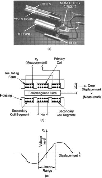
In its simplest form, the LVDT consists of an insulating, nonmagnetic “form” (a cylindrical structure on which a coil is wound, and is integral with the housing), which has a primary coil in the mid-segment and a secondary coil symmetrically wound in the two end segments.
The housing is made of magnetized stainless steel in order to shield the sensor from outside fields.
The primary coil is energized by an ac supply of voltage uref.
This will generate, by mutual induction, an act of the same frequency in the secondary coil. A core made of ferromagnetic material is inserted coaxially through the cylindrical form without actually touching it, as shown. As the core moves, the reluctance of the flux path changes.
The degree of flux linkage depends on the axial position of the core. Since the two secondary coils are connected in series opposition (as shown in Figure 6.9), so that the potentials induced in the two secondary coil segments oppose each other, it is seen that the net induced voltage is zero when the core is centered between the two secondary winding segments. This is known as the null position.
If the output signal is not demodulated, the direction is determined by the phase angle between the primary (reference) voltage and the secondary (output) voltage, which includes the carrier signal.
For an LVDT to measure transient motions accurately, the frequency of the reference voltage (the carrier frequency) has to be at least ten times larger than the largest significant frequency component in the measured motion, and typically can be as high as 20 kHz.
For quasi-dynamic displacements and slow transients on the order of a few hertz, a standard ac supply (at 60 Hz line frequency) is adequate.
The performance (particularly sensitivity and accuracy) is known to improve with the excitation frequency, however. Since the amplitude of the output signal is proportional to the amplitude of the primary signal, the reference voltage should be regulated to get accurate results.
