SKEDSOFT
Robot Classification
The physical structure of a robot may have anthropomorphic features, but this is a rather narrow perception. There is a particularly useful classification of industrial robots that is based on their kinematic structure.
For example, consider the classification shown in Figure.
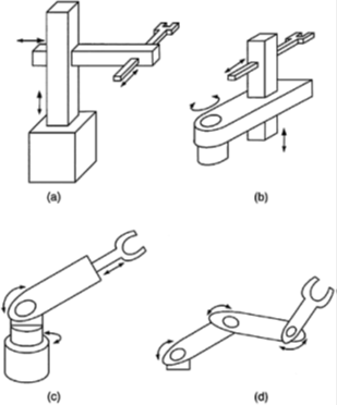
A kinematic classification for robotic manipulators. (a) Rectangular or Cartesian, (b) Cylindrical polar (R-P-P),
(c) Spherical polar (R-R-P), (d) Jointed spherical or articulated (3R).
Six degrees of freedom are required for a robot to arbitrarily position and orient an object in the three-dimensional space. It is customary to assign three of these degrees of freedom to the wrist that manipulates the end effector (hand), and the remaining three to the arm of the robot.
Since kinematic decoupling is desired for analytical simplicity, spherical wrists having three revolute (R) degrees of freedom with axes of motion coinciding at a single point (at the wrist) are commonly employed. Having decided on this configuration for the wrist, the kinematic structure of the arm can then be used as a basis for robot classification.
Specifically, the sequence of rotatory or revolute (R) joints and rectilinear or prismatic (P) joints employed in the arm structure will classify a robot. Four common classifications are shown in Figure: rectangular or Cartesian (3P), cylindrical (R-P-P or P-R-P), spherical or polar (R-R-P), and articulated or jointed spherical (3R).
Furthermore, selective compliant assembly robot arm (SCARA) configurations, where at least the first two of the three degrees of arm freedom do not face gravity (i.e., they employ vertical revolute axes or horizontal prismatic axes), are desired so that the actuators of the most demanding joints are not subjected to gravity loads.
Other classifications are possible as well. For example, robots may be classified according to the actuator type (e.g., hydraulic, dc servo, ac servo, stepper motor), by the transmission type (e.g., geared, direct-drive, harmonic-drive, timing-belt, chain and sprocket, tendoned, and traction-drive or friction-drive), by capacity and accuracy (e.g., heavy-duty industrial robots and microminiaturized finger robots), and by mobility (e.g., mobile robots and AGVs or automated guided vehicles).
Robotic tasks can be grouped broadly into (1) gross manipulation tasks and (2) fine manipulation tasks.
Control of the motion trajectory of the robot end effector is directly applicable to tasks in the first category. Examples of such tasks are seam tracking in arc welding, spray painting, contour cutting (e.g., laser and water jet) and joining (e.g., gluing, sewing, ultrasonic and laser merging), and contour inspection (e.g., ultrasonic, electromagnetic, and optical). Force and tactile
considerations are generally crucial to tasks in the second category.
Part assembly, robotic surgery, machining, forging, and engraving are examples of fine manipulation tasks. It is intuitively clear that gross manipulation can be accomplished through motion control. But force control (including compliance control) also would be needed for accurate fine manipulation, particularly because small motion errors can result in excessive and damaging forces in this class of tasks.
