SKEDSOFT
Series and Parallel Connections
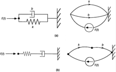
Let us consider two systems with a spring (k) and a damper (b). In Figure (a) they are connected in parallel, and in Figure (b) they are connected in series. Note their linear graphs as shown in the figure.
The linear graph in (a) has two primary loops (two elements in parallel), whereas in (b) it has only one loop, corresponding to all elements in series with the force. we note the differences in their node and loop equations. These observations should be intuitively clear, without even writing loop or node equations.
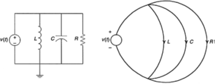
State Models From Linear Graphs
We can obtain a state model of a system from its linear graph. In particular, each branch in a linear graph is a “model” of an actual system element.
In mechanical systems it is common to use forces and velocities as state variables; specifically, the velocities of independent inertia elements in the system, and the forces associated with independent stiffness elements, because the state of an inertia element (mass element) can be represented by its velocity, and the state of a stiffness element (spring element) can be represented by its force.
Sign Convention
The important first step of developing a state-space model using linear graphs is indeed to draw a linear graph for the considered system.
A sign convention should be established, and as discussed before, a useful
convention is given below:
1. Power flows into the action point and out of the reference point of a system element. This direction is shown by an arrow (unless the element is a source).
2. Through variable (ƒ) and the across variable (u) are taken to be positive in the same direction at the action point as given by the linear graph arrow. At the reference point u is taken to be positive in the same direction as the linear-graph arrow, but ƒ is taken positive in the opposite direction.
3. Flow into a node is taken as positive (in writing node equations).
4. Loop direction is taken to be counterclockwise (in writing loop equations). Potential “drop” is taken as positive, which direction is the same as the linear-graph (branch) arrow, except for a source element (For a source, potential increases in the arrow direction).
Note that these are conventions which need to be established first. Then, the actual values of the variables could be positive or negative depending on their actual direction.
