SKEDSOFT
SYNCHRO TRANSFORMER
Synchro Transformer
The synchro is somewhat similar in operation to the resolver. The main differences are that the synchro employs two identical rotor stator pairs, and each stator has three sets of windings, which are placed 120° apart around the rotor shaft. A schematic diagram for Schematic diagram of a synchro-transformer.
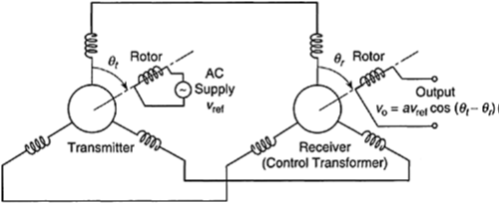
Both rotors have single-phase windings and, contrary to popular belief, the synchro is essentially a single-phase device. One of the rotors is energized with an ac supply voltage uref.
This induces voltages in the three winding segments of the corresponding stator. These voltages have different amplitudes, which depend on the angular position of the rotor but are in phase.
This drive rotor-stator pair is known as the transmitter. The other rotor-stator pair is known as the receiver or the control transformer.
Windings of the transmitter stator are connected correspondingly to the windings of the receiving stator This induces a voltage uo in the rotor of the receiver.
Suppose that the angle between the drive rotor and one set of windings in its stator is denoted by qt. The resultant magnetic field on the receiver stator will make the same angle with the corresponding winding of that stator.
If the receiver rotor is aligned with this direction (i.e., QR=qt), then the induced voltage uo will be maximum. If the receiver rotor is placed at 90° to this resultant magnetic field, then uo—0. Therefore, an appropriate expression for the synchro output is uo=aurefcos (qt-qr)
Synchros are operated near QR=qt 90°, where the output voltage is zero.
Hence, we define a new angle q such That
Synchro-transformers can be used to measure relative displacements between two rotating objects. For measuring absolute displacements, one of the rotors is attached to the rotating member (e.g., the shaft), while the other rotor is fixed to a stationary member (e.g., the bearing).
As is clear from the previous discussion, a zero reading corresponds to the case where the two rotors are 90° apart. Synchros have been used extensively in position servos, particularly for the position control of rotating objects. Typically, the input command is applied to the transmitter rotor.
The receiver rotor is attached to the object that is being controlled. The initial physical orientations of the two rotors should ensure that for a given command, the desired position of the object corresponds to zero output voltage uo, that is, when the two rotors are 90° apart.
