SKEDSOFT
Fibre design issues: its simplest form a step-index fibre consists of a cylindrical core surrounded by a cladding layer whose index is slightly lower than that of the core. Both core and cladding use silica as the basic material, the difference in the refractive indexes is realized by doping the core or the cladding or both. Dopants such as GeO2 and P2O5 increase the refractive index of silica and are suitable for the core. On the other hand, dopants such as B2O3 and fluorine decrease the refractive index of silica and are suitable for the cladding. The major design issues for the optical fibres are related to the refractive-index profile, to the amount of dopants, and the core and cladding dimensions. Figure 1 shows typical index profiles that have been used for different types of fibres.
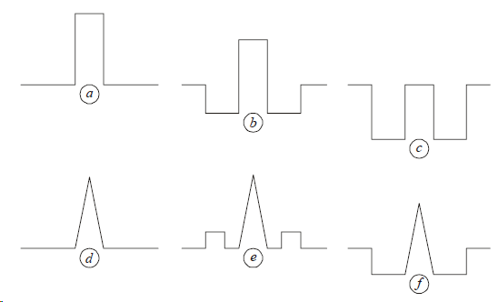
Figure 1 – Examples of index profiles of single-mode fibres
The top row corresponds to standard fibres which are designed for having minimum dispersion near 1300 nm with a cut-off wavelength in the range 1 100-1 200 nm. The simplest design (Figure 1a) consists of a pure silica cladding and a core doped with GeO2. A commonly used variation (Figure 1b) has a reduced cladding index over a region adjacent to the core by fluorine doping. It is also possible to have an undoped core using a design shown in Figure 1c. The fibres of these last two types are referred to as depressed cladding fibres. They are also called W fibres reflecting the shape of the index profile. The bottom row of Figure 1 shows three index profiles used for the dispersion-shifted fibres which have the zerodispersion wavelength in the range 1 450-1 600 μm. A step or triangular index profile with a depressed or raised cladding is often used for this purpose. The refractive indexes and the thicknesses of the different layers are optimized to design a fibre with the desirable dispersion characteristics.
Fibre manufacturing methods: Preparation of silica fibres consists of two major processes: preform making and drawing. The attenuation and the dispersion characteristics of optical fibres largely depend on the preform making process, while glass geometry characteristics and strength depend on the drawing process. These two processes are shortly described in the following.
Several methods can be used to make the preforms. The four commonly used methods are modified chemical-vapour deposition (MCVD), plasma-activated chemical-vapour deposition (PCVD), outside-vapour deposition (OVD) and vapour-axial deposition (VAD). The second process (drawing) of the preparation of a fibre is essentially the same, irrespective of the process used to make the preform. Figure 2 shows the drawing apparatus schematically.
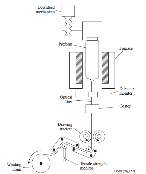 fig..(2)Apparatus for fibre drawing
The preform is fed into a furnace in a controlled manner where it is heated to a temperature of about 2 000° C. The melted preform is drawn into a fibre by using a precision-feed mechanism. The fibre diameter is monitored optically by dedicated measurement equipment. The fibre diameter can be kept constant to within 0.1%. A polymer coating is applied to the fibre during the drawing step. It serves a dual purpose, as it provides mechanical protection and preserves the transmission properties of the fibre. The diameter of the coated fibre is typically 245 μm, although it can be as large as 900 μm when multiple coatings are applied. A proof-stress which breaks weak spots is applied while the fibre is winding on the drum. This proof-stress can be applied either on-line during the drawing process, or off-line as a separate process step. The proof-test is a main reliability tool.
