SKEDSOFT
Additional Terms, Notations, and Assumptions: In most parts of this chapter, we ignore all the other factors that can cause a job to be blocked, so, no job ever suspends itself and every job is preemptable on the processor.
We will discuss the effect of self-suspension and nonpreemptivity at the end of the chapter. We sometimes use Jh and Jl to denote a higher-priority job and a lower-priority job, respectively. The priorities of these jobs are denoted by πh and πl , respectively. In general, the priority of a job Ji is πi . As in earlier chapters, we represent priorities by integers; the smaller the integer, the higher the priority.
A higher-priority job Jh is said to be directly blocked by a lower-priority job Jl when Jl holds some resource which Jh requests and is not allocated. In the example in Figure 8–2, J3 directly blocks J2 at time 5.
We describe the dynamic-blocking relationship among jobs using a wait-for graph. In the wait-for graph of a system, every job that requires some resource is represented by a vertex labeled by the name of the job. There is also a vertex for every resource in the system, labeled by the name and the number of units of the resource. At any time, the wait-for graph contains an (ownership) edge with label x from a resource vertex to a job vertex if x units of the resource are allocated to the job at the time. There is a (wait-for) edge with label y from a job vertex to a resource vertex if the job requested y units of the resource earlier and the request was denied. In other words, the job is waiting for the resource. (Clearly, y plus the sum of all the labels of edges from the resource vertex is larger than the number of units of the resource.) Therefore, a path in a wait-for graph from a higher-priority job to a lowerpriority job represents the fact that the former is directly blocked by the latter. A cyclic path in a wait-for graph indicates a deadlock.
The simple graph in Figure 8–5 is an example. It represents the state of the system in Figure 8–2 at time 5: The resource R is allocated to J3 and J2 is waiting for the resource. The path from J2 to J3 indicates that J2 is directly blocked by J3. Later, J1 will also be directly
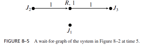
blocked by J3 when it requests and is denied the resource, and the wait-for graph of the system will have an additional edge from J1 to R. Since there is only one resource, deadlock can never occur.
In a system of periodic tasks, we say that a periodic task Ti has a critical section [R, x; y], or that the task requires x units of resource R for y units of time, if every job in the task requires at most x units of R for at most y units of time. We sometimes denote the periodic task by the tuple (φi , pi , ei , Di , [R, x; y]). In general, when jobs in the task require more than one resource and hence have more than one critical section, we put all the critical sections in the tuple. Hence if J2 in Figure 8–1 is a job in a periodic task of period 100, execution time 20, zero phase, and relative deadline 100, and if no job in the task has any longer critical section, we call the task (100, 20; [R2; 7[R3; 2]][R3; 3]). When the parameters of the critical sections are not relevant, we also denote the task Ti by a tuple (φi , pi , ei , Di ; ci ); the last element ci is the maximum execution time of the longest critical section of the jobs in the periodic task. (The execution times of all the critical sections are included in the execution time ei of the task.) In this simpler way, the task (100, 20; [R2; 7[R3; 2]][R3; 3]) is also called (100, 20; 7).
We will specify resource requirements of a system by a bipartite graph in which there is a vertex for every job (or periodic task) and every resource. Each vertex is named by the name of the job (or task) or resource it represents. The integer next to each resource vertex Ri gives the number νi of units of the resource. The fact that a job J (or task T ) requires a resource Ri is represented by an edge from the job (or task) vertex J (or T ) to the resource vertex Ri . We may label each edge by one or more 2-tuples or numbers, each for a critical section of the job (or task) which uses the resource. The first element of each 2-tuple gives the number of units used in the critical section. We usually omit this element when there is only 1 unit of the resource. The second element, which is always given, specifies the duration of the critical section. Figure 8–6 gives two examples. The simple graph in Figure 8–6(a) gives
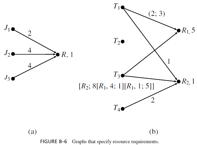
the resource requirements of the jobs in the system in Figure 8–2. The labels of the edges are the durations of the critical sections of the respective jobs. The graph in Figure 8-6(b) uses a combination of ways to specify resource requirements. The system has four periodic tasks. The edges from T1 tells us that (each job in) this task requires 2 units of R1 for at most 3 units of time and it requires the resource R2 for at most 1 unit of time. Similarly, T4 requires R2 for 2 units of time. Rather than specifying the resource requirement of T3 by complicated labels of edges connecting vertex T3 to resource vertices, we simply provide the information on critical sections of T3 next to the vertex T3. There is no edge from T2, meaning that this task does not require any resource.
Finally, to avoid verboseness whenever there is no ambiguity, by a critical section, we mean an outermost critical section. By a critical section of a periodic task, we mean a critical section of each job in the periodic task.
