SKEDSOFT
Crossbar-Connected System: Crossbar-connected System (illustrated in Figure 5) is a grid structure of processor and memory modules. The every cross point of grid structure is attached with switch. By looking at the Figure it seems to be a contention free architecture of multiprocessing system, it shows simultaneous access between processor and memory modules as N number of processors are provided with N number of memory modules. Thus each processor accesses a different memory module. Crossbar needs N2 switches for fully connected network between processors and memory. Processors may or may not have their private memories. In the later case the system supports uniform-memory-access.
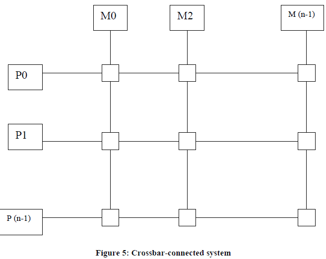
Where P= processor, M=Memory Module and =Switch
But Unfortunately this system also faces the problem of contention when,
1) More than two processors (P1 and P2) attempt to access the one memory module (M1) at the same time. In this condition, contention can be avoided by making any one processor (P1) deferred until the other one (P2) finishes this work or left the same memory module (M1) free for processor P1.
2) More than two processor attempts to access the same memory module. This problem cannot be solved by above-mentioned solution.
Thus in crossbar connection system the problem of contention occurs on at memory neither at processor nor at interconnection networks level. The solution of this problem includes quadratic growth of its switches as well as its complexity level. Not only this, it will make the whole system expensive and also limit the scalability of the system.
Hypercubes System
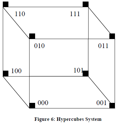
Hypercube base architecture is not an old concept of multiprocessor system. This architecture has some advantages over other architectures of multiprocessing system. As the Figure 6 indicates, the system topology can support large number of processors by providing increasing interconnections with increasing complexity. In an n-degree hypercube architecture, we have:
1) 2n nodes (Total number of processors)
2) Nodes are arranged in n-dimensional cube, i.e. each node is connected to n number of nodes.
3) Each node is assigned with a unique address which lies between 0 to2n –1
4) The adjacent nodes (n-1) are differing in 1 bit and the nth node is having maximum ‘n’ internode distance.
Let us take an example of 3-degree hypercube to understand the above structure:
1) 3-degree hypercube will have 2n nodes i.e., 23 = 8 nodes
2) Nodes are arranged in 3-dimensional cube, that is, each node is connected to 3 number of nodes.
3) Each node is assigned with a unique address, which lies between 0 to 7 (2n –1), i.e., 000, 001, 010, 011, 100, 101, 110, 111
4) Two adjacent nodes differing in 1 bit (001, 010) and the 3rd (nth ) node is having maximum ‘3’internode distance (100).
Hypercube provide a good basis for scalable system because its communication length grows logarithmically with the number of nodes. It provides a bi-directional communication between two processors. It is usually used in loosely coupled multiprocessor system because the transfer of data between two processors goes through several intermediate processors. The longest internodes delay is n-degree. To increase the input/output bandwidth the input/output devices can be attached with every node (processor).
Multistage Switch Based system
Multistage Switch Based System permits simultaneous connection between several input-output pairs. It consists of several stages of switches which provide multistage interconnection network. A N input-output connections contains K= log2N stages of N/2 switches at each stage. In simple words, N*N processor-memory interconnection network requires (N/2) x = log2N switches.
For example, in a 8×8 process-memory interconnection network requires (8/2* log28) = 4*3= 12 switches. Each switch acts as 2×2 crossbar.
This network can connect any processor to any memory module by making appropriate connection of each of the ‘K’ stages. The binary address of processor and memory gives binary string routing path between module pairs of input and output. the routing path id decided by on the basis of destination binary address, that the sender includes with each request for connection. Various combinations of paths between sources to destination are possible by using different switch function (straight, swap, copy, etc.)
In multistage switch based system all inputs are connected to all outputs in such a way that no two-processor attempt to access the same memory at the same time. But the problem of contention, at a switch, arises when some memory modules are contested by some fixed processor. In this situation only one request is allowed to access and rest of the requests are dropped. The processor whose requests were dropped can retry the request or if buffers are attached with each switch the rejected request is forwarded by buffer automatically for transmission. This Multistage interconnection networks also called store-and-forward networks.
