SKEDSOFT
Introduction:
The brake power measurement involves the determination of the torque and the angular speed of the engine output shaft. The torque measuring device is called a dynamometer. Dynamometers can be broadly classified into two main types, power absorption dynamometers and transmission dynamometer.
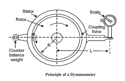
Principle of a Dynamometer
A rotor driven by the engine under test is electrically, hydraulically or magnetically coupled to a stator. For every revolution of the shaft, the rotor periphery moves through a distance 2pr against the coupling force F. Hence, the work done per revolution is

The external moment or torque is equal to S × L where, S is the scale reading and L is the arm. This moment balances the turning moment R × F, i.e.
S × L = R × F
Work done/revolution = 2p SL
Work done/minute = 2p SLN
where, N is rpm. Hence, power is given by
Brake power P = 2p NT
Absorption Dynamometers
These dynamometers measure and absorb the power output of the engine to which they are coupled. The power absorbed is usually dissipated as heat by some means. Example of such dynamometers is prony brake, rope brake, hydraulic dynamometer, etc.
Transmission Dynamometers
- In transmission dynamometers, the power is transmitted to the load coupled to the engine after it is indicated on some type of scale. These are also called torque-meters