SKEDSOFT
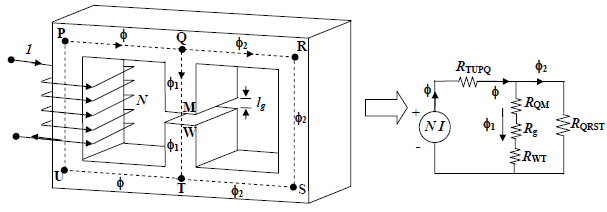
Analysis of series-parallel magnetic circuit: We now take up the following magnetic circuit (Figure A) which appears to be not so straight forward as the previous cases. As a first step to solve this circuit, we would like to draw its equivalent electrical representation. Vertical links of the core are called limbs and the horizontal links are called yoke of the magnetic circuit. In the figure PU, QT and RS are the limbs whereas PQ, QR, UT and TS are the yokes. It is customary to fix up the corner points P,Q,R etc from the given physical dimensions, joining of which will give you the mean length of the flux paths.
 fig(A)
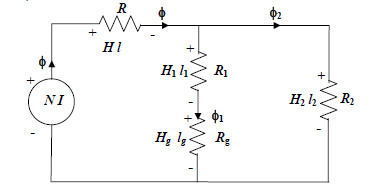
If the coil carries a current I in the direction shown, flux φ, produced in the first limb will be in the upward direction. Same φ is constrained to move along the yoke PQ. At point Q, two parallel paths are available to φ for its onwards journey namely (i) the central limb QT and (ii) the yoke QR. In other words, φ will be divided into two components φ1 and φ2 as shown with the obvious condition φ = φ1 φ2. The relative values of these components will be decided by respective reluctances of the paths. φ1 and φ2 once again recombine at point T and completes the path. Now in the path TUPQ flux φ is same, it is made of same material and has same cross sectional area A, then its reluctance ℜTU PQ ∞ TU PQlA. In the central limb, flux is same (φ1), however it encounters two materials, one is iron (QM and WT) and the other is a small air gap (MW). The reluctance of the air gap 0ggl=μAℜ. The two reluctances ℜQM and ℜWT of the magnetic material may however be combined into a single reluctance as ℜ1 = ℜQM ℜWT. The portion of the magnetic circuit which carries flux φ2 can be represented by a single reluctance ℜQRST ∞ QRSTlA. Instead of carrying on with long suffixes let us call ℜQRST to be ℜ2. To write down the basic equations let us redraw the electrical equivalence of the above magnetic circuit below (Figure B):
 fig(B)
