SKEDSOFT
Design procedures for lag compensation by the root-locus method
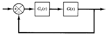
Fig: 1 control system
The procedure for designing lag compensators for the system shown in Figure 1 by the root-locus method may be stated as follows (we assume that the uncompensated system meets the transient-response specifications by simple gain adjustment:
1. Draw the root-locus plot for the uncompensated system whose open-loop transfer function is G(s). Based on the transient-response specifications, locate the dominant closed-loop poles on the root locus.
2. Assume the transfer function of the lag compensator to be
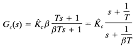
Then the open-loop transfer function of the compensated system becomes Gc(s)G(s).
3. Evaluate the particular static error constant specified in the problem.
4. Determine the amount of increase in the static error constant necessary to satisfy the specifications.
5. Determine the pole and zero of the lag compensator that produce the necessary increase in the particular static error constant without appreciably altering the original root loci. (Note that the ratio of the value of gain required in the specifications and the gain found in the uncompensated system is the required ratio between the distance of the zero from the origin and that of the pole from the origin.)
6. Draw a new root-locus plot for the compensated system. Locate the desired dominant closed-loop poles on the root locus. (If the angle contribution of the lag network is very small, that is, a few degrees, then the original and new root loci are almost identical. Otherwise, there will be a slight discrepancy between them. Then locate, on the new root locus, the desired dominant closed-loop poles based on the transient-response specifications.)
7. Adjust gain  of the compensator from the magnitude condition so that the dominant closed-loop poles lie at the desired location.
