SKEDSOFT
Speed control system
The basic principle of a Watt's speed governor for an engine is illustrated in the schematic diagram of Figure 1. The amount of fuel admitted to the engine is adjusted according to the difference between the desired and the actual engine speeds.
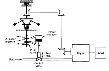
Fig: 1
The sequence of actions may be stated as follows: The speed governor is adjusted such that, at the desired speed, no pressured oil will flow into either side of the power cylinder. If the actual speed drops below the desired value due to disturbance, then the decrease in the centrifugal force of the speed governor causes the control valve to move downward, supplying more fuel, and the speed of the engine increases until the desired value is reached. On the other hand, if the speed of the engine increases above the desired value, then the increase in the centrifugal force of the governor causes the control valve to move upward. This decreases the supply of fuel, and the speed of the engine decreases until the desired value is reached. In this speed control system, the plant (controlled system) is the engine and the controlled variable is the speed of the engine. The difference between the desired speed and the actual speed is the error signal. The control signal (the amount of fuel) to be applied to the plant (engine) is the actuating signal. The external input to disturb the controlled variable is the disturbance. An unexpected change in the load is a disturbance.
Robot control system
Industrial robots are frequently used in industry to improve productivity. The robot can handle monotonous jobs as well as complex jobs without errors in operation. The robot can work in an environment intolerable to human operators. For example, it can work in extreme temperatures (both high and low) or in a high- or low-pressure environment or under water or in space. There are special robots for firefighting, underwater exploration, and space exploration, among many others.
The industrial robot must handle mechanical parts that have particular shapes and weights. Hence, it must have at least an arm, a wrist, and a hand. It must have sufficient power to perform the task and the capability for at least limited mobility. In fact, some robots of today are able to move freely by themselves in a limited space in a factory.
The industrial robot must have some sensory devices. In low-level robots, micros witches are installed in the arms as sensory devices. The robot first touches an object and then, through the micro switches, confirms the existence of the object in space and proceeds in the next step to grasp it.
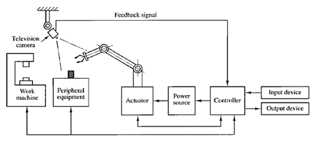
Fig: 2
In a high-level robot, an optical means (such as a television system) is used to scan the background of the object. It recognizes the pattern and determines the presence and orientation of the object. A computer is necessary to process signals in the pattern-recognition process (see Figure 2). In some applications, the computerized robot recognizes the presence and orientation of each mechanical part by a pattern-recognition process that consists of reading the code numbers attached to it. Then the robot picks up the part and moves it to an appropriate place for assembling, and there it assembles several parts into a component. A well-programmed digital computer acts as a controller.
