SKEDSOFT
Procedures for drawing a block diagram:
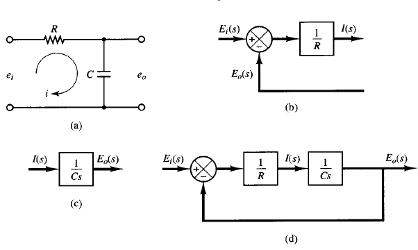
Fig: 1 (a) RC circuit; (b) block diagram representing Equation I(s); (c) block diagram representing Equation E0(s); (d) block diagram of the RC circuit.
To draw a block diagram for a system, first write the equations that describe the dynamic behavior of each component. Then take the Laplace transforms of these equations, assuming zero initial conditions, and represent each Laplace-transformed equation individually in block form. Finally, assemble the elements into a complete block diagram.
As an example, consider the RC circuit shown in Figure 1(a). The equations for this circuit are
The Laplace transforms of the above equations, with zero initial condition, becomes
Equation of I(s) represents a summing operation, and the corresponding diagram is shown in Figure 1(b). Equation E0(s) represents the block as shown in Figure 1(c). Assembling these two elements, we obtain the overall block diagram for the system as shown in Figure 1(d).
