SKEDSOFT
Root loci for positive-feedback systems
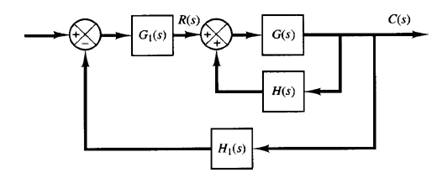
Fig: 1 Control system
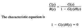
In a complex control system, there may be a positive-feedback inner loop as shown in Figure 1. Such a loop is usually stabilized by the outer loop. In what follows, we shall be concerned only with the positive-feedback inner loop. The closed-loop transfer function of the inner loop is
This equation can be solved in a manner similar to the development of the root-locus method. The angle condition, however, must be altered.
The characteristics equation can be rewritten as
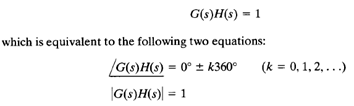
The total sum of all angles from the open-loop poles and zeros must be equal to 0° ± k360°. Thus the root locus follows a 0° locus in contrast to the 180° locus considered generally. The magnitude condition remains unaltered.
To illustrate the root-locus plot for the positive feedback system, let us consider the following transfer functions G(s) and H(s) as an example.
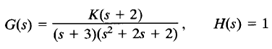
The gain K is assumed to be positive.
The general rules for constructing root loci must be modified in the following way:
Rule 2 is modified as follows: If the total number of real poles and real zeros to the right of a test point on the real axis is even, then this test point lies on the root locus.
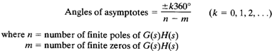
Rule 3 is modified as follows:
Rule 5 is modified as follows: When calculating the angle of departure (or angle of arrival) from a complex open-loop pole (or at a complex zero), subtract from 0° the sum of all angles of the vectors from all the other poles and zeros to the complex pole (or complex zero) in question, with appropriate signs included.
