SKEDSOFT
System compensation
Setting the gain is the first step in adjusting the system for satisfactory performance. In many practical cases, however, the adjustment of the gain alone may not provide sufficient alteration of the system behavior to meet the given specifications. As is frequently the case, increasing the gain value will improve the steady-state behavior but will result in poor stability or even instability. It is then necessary to redesign the system (by modifying the structure or by incorporating additional devices or components) to alter the overall behavior so that the system will behave as desired. Such a redesign or addition of a suitable device is called compensation. A device inserted into the system for the purpose of satisfying the specifications is called a compensator. The compensator compensates for deficit performance of the original system.
Series (cascade) compensation and feedback (or parallel) compensation
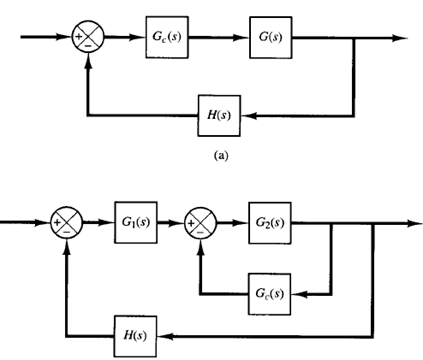
Fig: 1 (a) Series compensation; (b) feedback or parallel compensation
Figures 1 (a) and (b) show compensation schemes commonly used for feedback control systems. Figure 1(a) shows the configuration where the compensator Gc(s) is placed in series with the plant. This scheme is called series compensation. An alternative to series compensation is to feed back the signal(s) from some element(s) and place a compensator in the resulting inner feedback path, as shown in Figure 1(b). Such compensation is called feedback compensation or parallel compensation.
In compensating control systems, we see that the problem usually boils down to a suitable design of a series or feedback compensator. The choice between series compensation and feedback compensation depends on the nature of the signals in the system, the power levels at various points, available components, the designer's experience, economic considerations, and so on.
In general, series compensation may be simpler than feedback compensation; however, series compensation frequently requires additional amplifiers to increase the gain and/or to provide isolation. (To avoid power dissipation, the series compensator is inserted at the lowest energy point in the feedforward path.)
Note that, in general, the number of components required in feedback compensation will be less than the number of components in series compensation, provided a suitable signal is available, because the energy transfer is from a higher power level to a lower level. (This means that additional amplifiers may not be necessary.)
In discussing compensators, we frequently use such terminologies as lead network, lag network, and lag-lead network. If a sinusoidal input ei is applied to the input of a network and the steady-state output eo (which is also sinusoidal) has a phase lead, then the network is called a lead network. (The amount of phase lead angle is a function of the input frequency.) If the steady-state output eo has a phase lag, then the network is called a lag network. In a lag-lead network, both phase lag and phase lead occur in the output but in different frequency regions; phase lag occurs in the low-frequency region and phase lead occurs in the high-frequency region. A compensator having a characteristic of a lead network, lag network, or lag-lead network is called a lead compensator, lag compensator, or lag-lead compensator.
