SKEDSOFT
Typical pole-zero configurations and corresponding root loci
Several open-loop pole-zero configurations and their corresponding root loci in Table 1
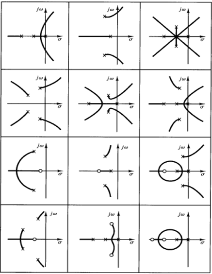
Table 1: Open-Loop Pole-Zero Configurations and the Corresponding Root Loci
The pattern of the root loci depends only on the relative separation of the open-loop poles and zeros. If the number of open-loop poles exceeds the number of finite zeros by three or more, there is a value of the gain K beyond which root loci enter the right-half s plane, and thus the system can become unstable. A stable system must have all its closed-loop poles in the left-half s plane.
Note that once we have some experience with the method we can easily evaluate the changes in the root loci due to the changes in the number and location of the open loop poles and zeros by visualizing the root-locus plots resulting from various pole-zero configurations.
