SKEDSOFT
Band-Pass Filters
An ideal band-pass filter passes all signal components within a finite frequency band and blocks off all signal components outside that band.
The lower frequency limit of the pass band is called the lower cutoff frequency (wc1) and the upper frequency limit of the band is called the upper cutoff frequency (wc2).
The most straightforward way to form a band-pass filter is to cascade a high-pass filter of cutoff frequency wc1 with a low-pass filter of cutoff frequency wc2. Such an arrangement is shown in Figure.
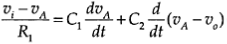
The passive circuit shown in Figure (a) is obtained by connecting together the circuits shown in Figure (a).
The active circuit shown in Figure (b) is obtained by connecting a voltage follower op-amp circuit to the original passive circuit.
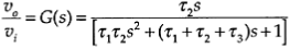
Passive and active filters have the same transfer function, assuming that loading problems (component interaction) are not present in the passive filter.
Since loading errors and interactions can be serious in practice, however, the active version is preferred.
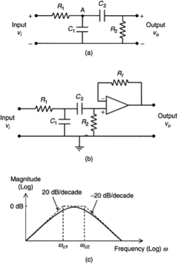
Band-pass filter: (a) A basic passive filter stage, (b) A basic active filter stage, (c) Frequency response
characteristic.