SKEDSOFT
Rotatory-Variable Differential Transformer (RVDT)
The RVDT operates using the same principle as the LVDT, except that in an RVDT, a rotating ferromagnetic core is used. The RVDT is used for measuring angular displacements.
The rotating core is shaped such that a reasonably wide linear operating region is obtained. Advantages of the RVDT are essentially the same as those cited for the LVDT.
Since the RVDT measures angular motions directly, without requiring nonlinear transformations (which is the case in resolvers, as will be discussed subsequently), its use is convenient in angular position servos.
The linear range is typically ±40° with a nonlinearity error less than ±0.5% of full scale.
In variable-inductance devices, the induced voltage is generated through the rate of change of the magnetic flux linkage. Therefore, displacement readings are distorted by velocity; similarly, velocity readings are affected by acceleration.
For the same displacement value, the transducer reading will depend on the velocity at that displacement. This error known as the rate error, increases with the ratio (cyclic velocity of the core)/(carrier frequency).
Hence, the rate error can be reduced by increasing carrier frequency.
The reason for this is as follows:
At high frequencies, the induced voltage due to the transf former effect (having frequency of the primary signal) is greater than the induced voltage due to the rate (velocity) effect of the moving member.
Hence the error will be small. To estimate a lower limit for the carrier frequency in order to reduce rate effects, we may proceed as follows:
1. For an LVDT:Let
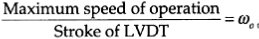
The excitation frequency of the primary coil should be chosen 5wo or more.
2. For an RVDT:For above, use the maximum angular frequency of operation (of the rotor).
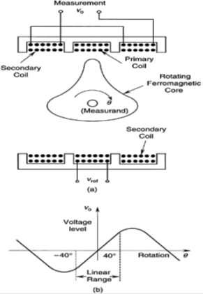
(A) SCHEMATIC DIAGRAM OF AN RVDT, (B) OPERATING CURVE.
