SKEDSOFT
Numerical aperture: The numerical aperture (NA) is the sine of the vertex half-angle of the largest cone of rays that can enter or leave the core of an optical fibre, multiplied by the refractive index of the medium in which the vertex of the cone is located. All values are measured at 850 nm. The value of the numerical aperture is about 5% lower than the value of the maximum theoretical numerical aperture NAtmax which is derived from a refractive index measurements trace of the core and cladding:
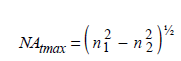
in which n1 is the maximum refractive index of the core and n2 is the refractive index of the innermost homogeneous cladding.
Macrobending loss: For single-mode fibres macrobending loss varies with wavelength, bend radius and number of turns about a mandrel with a specified radius. Therefore, the limit for the macrobending loss is specified in ITU-T Recommendations for defined wavelength(s), bend radius, and number of turns.
The recommended number of turns corresponds to the approximate number of turns deployed in all splice cases of a typical repeater span. The recommended radius is equivalent to the minimum bend-radius widely accepted for long-term deployment of fibres in practical systems installations to avoid static-fatigue failure. For multimode fibres the launch condition is of paramount importance for macrobending loss, in particular the presence of higher order modes which are the most sensitive being stripped off due to bending. The mode distribution encountered at a specific macrobend may depend on how many macrobends precede it. For example, the first bend might influence the launch condition at the second bend, and the second bend might influence the launch condition at the third bend, etc. Consequently, the macrobending added loss at a given bend might be different than the macrobending added loss at another bend. In particular, the first bend may have the largest influence on following bends. Consequently, the macrobending added loss produced by multiple bends should not be expressed in the units of “dB/bend” by dividing the total added loss by the number of bends, but in dB for the specified number of bends.
Fibre and protective materials: The substances of which the fibres are made should be known because care may be needed in fusion splicing fibres of different substances. However adequate splice loss and strength can be achieved when splicing different high-silica fibres.
The physical and chemical properties of the material used for the fibre primary coating and the best way of removing it (if necessary for the splicing of the fibres) should be indicated. The primary coating is made by the layer(s) of protective coating material applied to the fibre cladding
during or after the drawing process to preserve the integrity of the cladding surface and to give a minimum amount of required protection (e.g. a 250 μm protective coating). A secondary coating made by layer(s) of coating material can be applied over one or more primary coated fibres in order to give additional required protection or to arrange fibres together in a particular structure, e.g. a 900 μm “buffer” coating, “tight jacket”, or a ribbon coating (see Chapter 2).
