SKEDSOFT
Twymann-Green Interferometer : A set up for the Twyman-Green interferometer is shown in (Fig.A(a)). The interferometer is used to test the flat surfaces, beam splitters, prism and lens. Light from a source S is collimated using lens L1 which falls on a beam splitter and is divided into two beams which move towards mirrors M1 & M2 respectively. These beams are then reflected back and combine again at beam splitter. Another lens L2 is used to project the fringe pattern on screen. The mirrors and beam splitters used in the set up are of high optical quality. Interference phenomenon takes place between two plane waves. A monochromatic source (such as laser light) or quasi monochromatic source (such as mercury vapour lamp along with different color filters to select desired ![]() ) is used to observe interference fringes. The straight line fringes are obtained when the plane waves enclose a small angle. The orientation of these fringes can be varied by changing the orientation of one mirror with respect to the other (finite fringe setting). The test surfaces/optical elements are introduced in the path of one beam. The various arrangements for different elements are shown in the (Fig.A(b))
) is used to observe interference fringes. The straight line fringes are obtained when the plane waves enclose a small angle. The orientation of these fringes can be varied by changing the orientation of one mirror with respect to the other (finite fringe setting). The test surfaces/optical elements are introduced in the path of one beam. The various arrangements for different elements are shown in the (Fig.A(b))
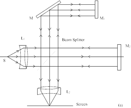 Fig.A (a) The Twyman-Green Inferometer
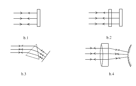
Fig.A (b) Various configurations to test a (b.1) Flat Surface (b.2) Beam Splitter (b.3) Prism (b.4) Lens
To test a flat surface, mirror M2 is replaced by the flat surface and the alignment is done to obtain a fringe pattern as shown in (Fig. A(b.1)), the flatness of the surface is given by ![]() . If the surface is irregular, the fringe shape is also irregular as these fringes are loci of constant thickness.
. If the surface is irregular, the fringe shape is also irregular as these fringes are loci of constant thickness.
A beam splitter is to be tested for the angle of it as well as to check if it introduces any deformation of wave front due to surface imperfection or refractive index inhomogeneities, First the interferometer is set for infinite fringe setting (ie when both the plane waves propagate along the same direction). Now the beam splitter is introduced in front of a mirror, normally. If there is no distortions of wave front due to beam splitter straight line fringes will be observed with fringe width given by ![]() where
where ![]() is angle of the wedge (Fig.A(b)).
is angle of the wedge (Fig.A(b)).
A prism is to be tested for the collimation. Any incident collimated beam should emerge out as collimated to test the prism. The testing configuration should be such that it retro reflect the beam to compare it with the reference beam. The experimental arrangement is shown in (Fig.A(b.3)) The wave front distortions could be due to surface imperfections of both the surfaces (entrance and exit surfaces) and refraction index inhomogeneities. A good prism should provide straight line fringes.
A lens is to be tested for aberrations. It means that a collimated beam incident on lens will not focus on one point but will have finite distribution. Also a point source at the focus of lens will not give a collimated beam. To check for the chromatic aberrations, the test lens is placed such that beam is retro reflected. The plane mirror in interferometer is replaced by a convex mirror and experimental arrangement is shown in the (Fig.A(b.4)). The interferogram is analysed to obtain the aberration coefficients.
