SKEDSOFT
Motional Emf: Consider a straight conductor AB moving along the positive x-direction with a uniform speed ![]() . The region is in a uniform magnetic field pointing into the plane of the page, i.e. in
. The region is in a uniform magnetic field pointing into the plane of the page, i.e. in ![]() direction.
direction.
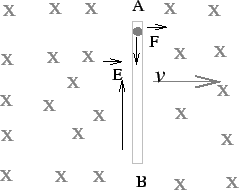
The fixed positive ions in the conductor are immobile. However, the negatively charged electrons experience a Lorentz force ![]() , i.e. a force along the
, i.e. a force along the ![]() direction. This pushes the electrons from the end A to the end B, making the former positive with respect to the latter. Thus an induced electric field is established in the conductor along the positive
direction. This pushes the electrons from the end A to the end B, making the former positive with respect to the latter. Thus an induced electric field is established in the conductor along the positive ![]() direction. The acceleration of electrons would stop when the electric field is built to a strength which is strong enough to annul the magnetic force. This electric field
direction. The acceleration of electrons would stop when the electric field is built to a strength which is strong enough to annul the magnetic force. This electric field ![]() is the origin of what is known as motional emf . The motion of charges finally stops due to the resistance of the conductor
is the origin of what is known as motional emf . The motion of charges finally stops due to the resistance of the conductor
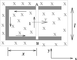
If the conductor slides along a stationary U- shaped conductor, the electrons find a path and a current is established in the circuit. The moving conductor thereby becomes a seat of the motional emf. We may calculate the emf either by considering the work that an external agency has to do to keep the sliding conductor move with a uniform velocity or by direct application of Faraday's law.
If the induced current is ![]() , a force
, a force ![]() acts on the wire in the negative x direction. In order to maintain the uniform velocity, an external agent has to exert an equal and opposite force on the sliding conductor. Since the distance moved in time
acts on the wire in the negative x direction. In order to maintain the uniform velocity, an external agent has to exert an equal and opposite force on the sliding conductor. Since the distance moved in time ![]() is
is ![]() , the work done by the external agency is
, the work done by the external agency is
![]()
where ![]() is the amount of charge moved by the seat of emf along the direction of the current. The emf is an electric potential difference.
is the amount of charge moved by the seat of emf along the direction of the current. The emf is an electric potential difference.
Thus, the emf is equivalently the work done in moving a unit charge. Thus,

This emf corresponds to the potential difference beteen the ends A and B.
An alternate derivation of the above is to consier the flux linked with closed circuit. Taking the origin at the extreme left end of the circuit, the area of the circuit in the magnetic field is ![]() where
where ![]() is the distance of the sliding rod from the fixed end. The flux linked with the circuit is, therefore,
is the distance of the sliding rod from the fixed end. The flux linked with the circuit is, therefore, ![]() . The rate at which flux changes is therefore given by
. The rate at which flux changes is therefore given by
![]()
If ![]() is not perpendicular to the plane of the circuit, we will need to take the perpendicular component of
is not perpendicular to the plane of the circuit, we will need to take the perpendicular component of ![]() in the above formula.
in the above formula.
Note that, in the illustration above, the magnetic flux linked with the circuit is increasing with time in the negative z direction. The direction of the induced current is, therefore, such that the magnetic field due to the current is along the positve z-direction, which will oppose increase of flux. Hence the current, as seen from above, is in the anticlockwise direction.
